
Instruction Manual


I 0709 - 5
2
2a
TOUCH
GB
2 - START-UP
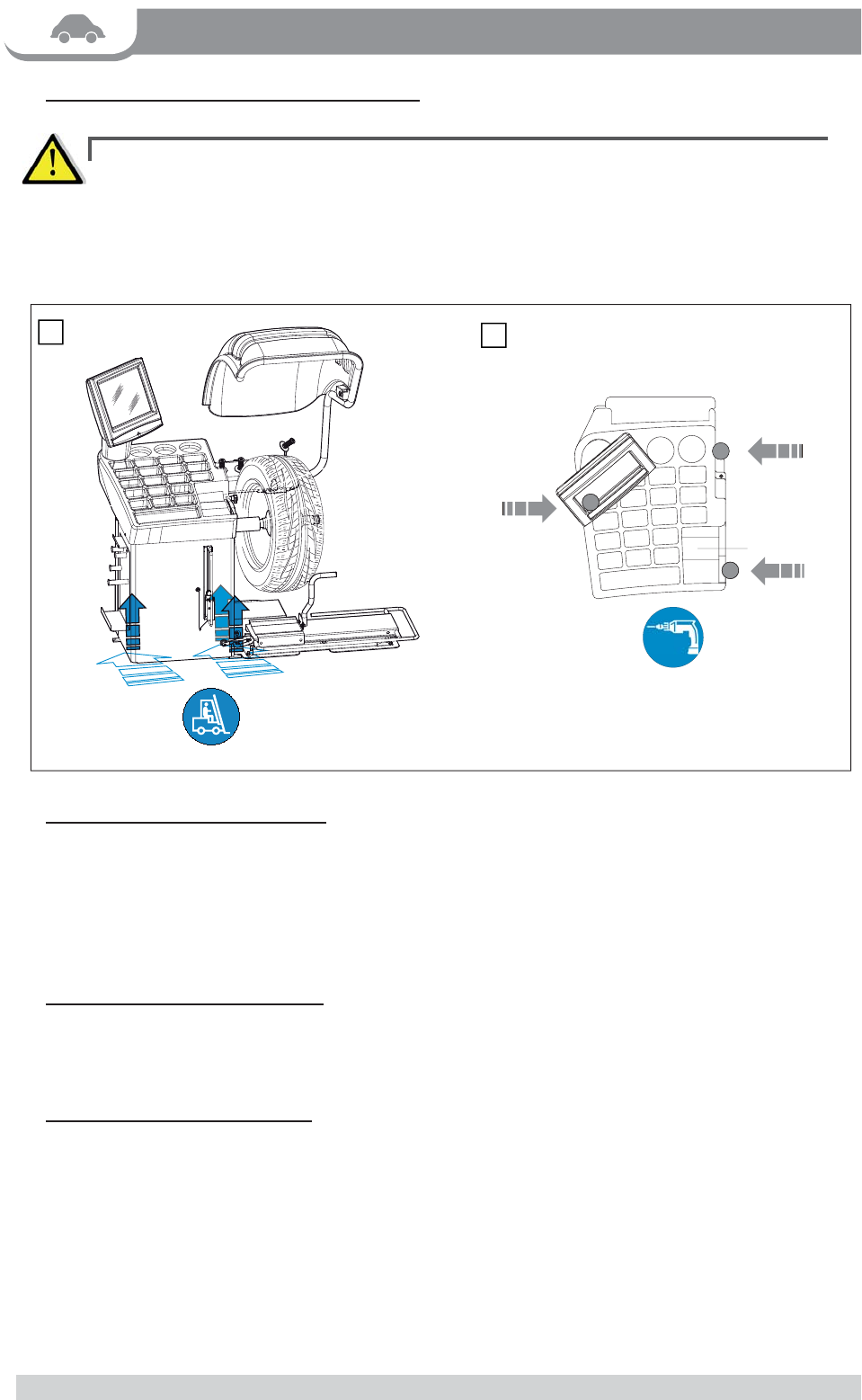
2.1 - HANDLING, LIFTING AND ANCHORING ►
T
O LIFT THE MACHINE, LEVER ONLY ON THE BASE WHERE THE 3 SUPPORT POINTS ARE LOCATED. NEVER, UNDER ANY ▪
CIRCUSTANCE, APPLY FORCE TO OTHER POINTS SUCH AS THE SPINDLE, HEAD, OR ACCESSORY SHELF.
C
HECK THAT THE BALANCING MACHINE TOUCHES THE FLOOR AT THE THREE SUPPORT POINTS. ▪
IT IS ADVISABLE TO ANCHOR TO THE FLOOR USING RELATIVE MOUNTING FEET (SEE FIG. 2A) IN THE EVENT OF CONTINUAL ▪
USE WITH WHEELS WEIGHING OVER 35 KG.
2.2 - ELECTRICAL CONNECTION ►
The machine is supplied with a single phase mains cable plus earth (ground) (any extension cables must have a
cross-section of not less than 2.5 mm
2
).
The supply voltage (and mains frequency) is given on the machine nameplate. It may NOT be changed.
Connection to the mains should always be made by expert personnel.
The machine should not be started up without proper earth (ground) connection.
Connection to the mains should be through a slow acting safety switch rated at 16A (230V).
2.3 - PNEUMATIC CONNECTION ►
For operation of the spindle with pneumatic locking (constant thrust air spring) connect the balancing machine to the
compressed air main. The connection fi tting is located at the back of the machine. A pressure of at least 8 kg/cm
2
(approx.
0.8 MPa or 8 BAR or 115 PSI) is required for correction operation of the release device.
2.4 - EXTRA SAFETY DEVICES ►
T ▪ he wheel is always locked even when there is a pressure or power failure during the balancing cycle.
Always actuate the unlocking control pedal with the machine stationary in order to avoid stress and ▪
abnormal wear on the adapter
.
2.4
► .1 - MANUAL CHUCK RELEASE
If the power fails, operate as described below to release a mounted wheel :
Remove the cover on the rear of the base ▪
Manually turn the controls 1 and 2 located on the valve ▪
Remove the released wheel ▪
Turn the controls back to the original position ▪