
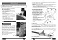
Operating instructions


9.1)
I
nstruction for drillin
g
close to rail heads
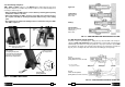
7. RAIL DRILL TYPE LD-2E ; LD-2E-110 ; LD-4EF
Code n. LD-2E ; LD-2E-110 ; LD-4EF each cover a basic drill (see page 1) complete
with the moving arm device DBG-F2 for clamping to the rail web and the track fi ttings
(Ref. to Fig. 12).
The DBG-F2 clamping device consists of:
– Clamping unit
– Type TDB 1 end piece
– Type TDB 3 end piece
– Type TDB 6 standard end piece
– Socket head cap screws M 8x25 (2 pcs)
– Spring washers (4 pcs)
– Reference pin
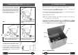
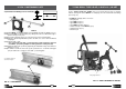
FIG. 12 – DRILL WITH DBG-F2 DEVICE
reference
pin
TDB 3
TDB 1
TDB 6
M 8x25 screws
and spring washers
21 14
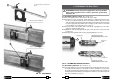
reference
pin
TDB 3
TD
B
1
TDB 6
M 8x25 screws
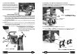
FIG. 21
02
03
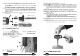
9. SPA... POSITIONING PLATE
FIG. 22 – POSITIONING
02
For clarity the drill is not
shown in the fi gures
9.1.1) Fit the MPAF... positioning template corresponding to the rail to be drilled(see § 7.3).
9.1.2) Insert the SPA... positioning plate (03) relating to the rail to be drilled in the appro-
priate housing (see Fig. 21).
9.1.3) Insert the locking pin (02) in one of the two holes in the positioning plate.
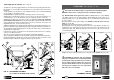
9.1.4) With the spindle fully withdrawn position the drill close to the rail head without
clamping it.
9.1.5) Slide the drill so that:
– the curved end of the SPA... positioning plate is fl ush against the rail head.
– the MPAF... positioning template is fl ush against the locking bolt (02).
9.1.6) Clamp the drill in this position by tightening the hand-wheel fully, and commence
drilling (see § 8.1).
9.1.7) To drill the second hole in the rail, repeat operations 9.1.5 - 6 with the locking pin
(02) inserted in the second hole of the SPA... positioning plate.