
Operating instructions


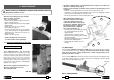
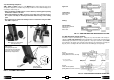

TDB 3 end piece
for enlarging existing holes
on rails inherent in the application
of electrical connections and for
additional special applications.
TDB 1 end piece for switch blades
and composite frogs
TDB 6 end piece for rails and stock rails
Seats to be used for
special applications.
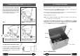
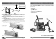
FIG.13 – ASSEMBLY END PIECES
positioning pawl
pointing downwards
holding
plate
7.1) Assembling end pieces
TDB 1, TDB 6 and TDB 3 end pieces of the DBG-F2 device, with moving arm, have been
designed for adaptation to the different operating conditions on rails and track fi ttings; their
assembly is shown in Fig. 13.
• When assembling the TDB 3 end piece ensure that the positioning pawl is pointing
downward in relation to the bolt.
• When disassembling the TDB 6 end piece ensure that, after removing the pivot,
the complete assembly is slid away downwards without acting on the holding
plate.
• Over-advancing the spindle after drilling must be avoided when using the TDB 1
and TDB 3 end pieces.
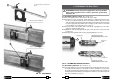
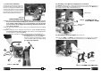
15 20
Start drilling
with discharge of
lubrocoolant
Drilling
Finish drilling
with removal of swarf and
switching off of
lubrocoolant
Approach
FIG. 19 – COOLANT DRILLING WITH BROACH CUTTER
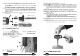
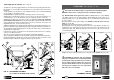
8.3) Drill fi tted with special spiral bit
Follow the sequence described in § 8.1, taking care to position the drill on the rail by ke-
eping the spindle fully withdrawn. Bear in mind that the coolant circuit, instead of being
automatically opened and closed by the guide bit, is kept open at all times by the DPE
spacer fi tted on the spigot of the spiral bit; it must therefore be activated, by opening the
tap (02), before starting to drill, then switched off after drilling by closing the tap.
FIG. 20b
PE 170 - PE 275 spiral bits
(drilling diameters from 17 to 27.5 mm)
FIG. 20 – COOLANT DRILLING WITH SPIRAL BIT
FIG. 20a
PE 70 - PE 165 spiral bits
(drilling diameters from 7 to 16.5 mm)
DPE spacer
APE adapter
Spiral bit
*
use only for APE...,
not required for APED...
*