
Operating instructions


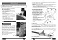
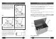
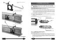
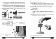
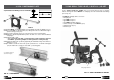
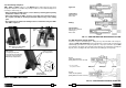
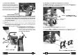
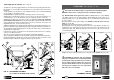

FIG. 15 – ASSEMBLY OF TEMPLATES
screws M6x16
reference
pin
MPAF...
MPAU
FIG. 14 – ASSEMBLY OF THE
TYPE “DBG-F2” CLAMP
Drilling machine
front plate
DBG-F2 Clamp
30
7.2) Assembly of the DBG-F2 clamping device on the drill
The DBG-F2 clamping device is fi tted to the front plate of the drill, centred by means of
the reference pin supplied and secured with the two socket head cap screws M8x25 (30)
also supplied. The assembly is illustrated in Fig. 14.
7.3) Assembly positioning templates (Ref. to Fig. 15)
7.3.1) The type MPAF.. and MPAU positioning templates are secured to the front plate
(04) of the drill by means of the two socket head cap screws M 6x16 supplied.
19 16
8.1.5) ONLY FOR LD-4EF DRILL
Set the motor speed, by means of the selec-
tor switch under the automatic switch (see
Fig. 17e), in correlation to the diameter of the
hole to be. We suggest to use the standard
speed (280 rpm) for holes smaller than ø 28
mm and the lower speed (250 rpm) for holes
between dia 28 and 40 mm inclusive.
8.1.6) Proceed to drill by initially applying light pressure on the lever (36), increasing
the pressure progressively, avoiding jolts, and fi nally relieving the pressure
in the exit phase. When drilling close to raised markings on the rail the initial
pressure must be extremely light until the markings disappear, otherwise the
cutter may be damaged.
8.1.7) The guide bit will enable the lubrocoolant to be discharged throughout the drilling
process.
8.1.8) When drilling has been completed, fully retract the spindle, stop the motor by
pressing the automatic switch (position " 0 "), and make sure that drilling swarf
is removed before recommencing drilling.
8.1.9) After drilling it is advisable to remove all swarf from the tool and spindle area.
8.2) Drill fi tted with “long” type broach cutter
(for drilling thicknesses of up to 50 mm).
Follow the sequence described in § 8.1, taking
care to position the drill on the rail by keeping
the spindle fully withdrawn.
36
35
02
39
ONLY FOR LD-4EF DRILL:
switch for changing of the spindle speed
FIG. 17e
SPEED CHANGE SWITCH
FIG. 18 – DRILLING