www.cembre.com Cembre S.p.A. Via Serenissima, 9 25135 Brescia (Italia) Telefono: 030 36921 Telefax: 030 3365766 E-mail: info@cembre.com www.cembre.it Cembre España S.L. Calle Verano, 6 y 8 - P.I. Las Monjas 28850 Torrejón de Ardoz - Madrid (España) Teléfono: 91 4852580 Telefax: 91 4852581 E-mail: info@cembre.es www.cembre.es Cembre Ltd. Dunton Park Kingsbury Road, Curdworth - Sutton Coldfield West Midlands B76 9EB (Great Britain) Tel.: 01675 470440 - Fax: 01675 470220 E-mail: sales@cembre.co.uk www.cembre.
WARNINGS APPENDIX “A” – Before using the drill, carefully read the instructions contained in this manual. SAVE THESE INSTRUCTIONS: this manual contains important safety and operating instructions for the drill. – STOP THE ENGINE when servicing the drill: before removing the broach cutters, spiral bits, positioning templates etc. – During operation keep hands away from the danger zone. – Always wear protective glasses and work gloves. – Avoid wearing clothes which may present a risk to personal safety.
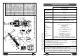
Qty 1 1 1 1 2 2 2 2 2 4 2 4 1 1 1 1 1 1 1 1 1 1 1 2 2 1 2 1 1 1 1 1 1 1 1 Description Spacer Blocking screw Complete bush Spring support spacer Spring M 5 self-locking nut Pin ø 8x50 cilindrical pin M5 ball dowell M 6x18 screw M 8x25 screw ø 8 elastic washer ø 4x10 cylindrical pin ø1,8x35 split pin TDB 1 termination ø1,8x35 split pin TDB 6 terminatin Split pin TDB 3 termination ø10 circlip Pin Left support shoulder Right support shoulder Blocking side plate Pin M 8x10 grub screw Handgrip Hand-wheel Block
2. ACCESSORIES SUPPLIED WITH THE DRILL 11 2.1) Guide bits for controlling the cooling system: for broach cutters suitable for drilling thicknesses of up to 25 mm – 1 pc PP 1, diameter 7 mm – 1 pc PP 2, diameter 8 mm for broach cutters suitable for drilling thicknesses of up to 50 mm – 1 pc PPL 1, diameter 7 mm – 1 pc PPL 2, diameter 8 mm 12 13 2.2) Spacer, type DPE, for controlling the cooling system with special spiral bits, diam. 7 ÷ 27,5 mm. 14 2.
3. ACCESSORIES TO BE ORDERED SEPARATELY 3.1) DBG-F2 device (*) with moving arm for clamping the drill to the rail web and track fittings, complete with the following end pieces: – TDB 1: for switch blades and compound frogs. – TDB 3: for repairing (adjusting) existing holes on rails for subsequent application of electrical connections and for additional special applications. – TDB 6: standard end piece for rails and stock rails. 10 09 (*) Supplied with drilling machine ref.
13.2.6) Checking of screws – Check and re-tighten all screws where necessary. 3.5) Templates for positioning the drill on the rails and stock rails to enable drilling to be carried out according to the provisions of railway boards standards: e.g.: – MPAF UIC54 on DRILLING AXIS of 54E1 rail – MPAF UIC60 on DRILLING AXIS of 60E1 rail 13.3) SPECIAL MAINTENANCE OF THE DRILL The special maintenance operations require the intervention of qualified personnel only, please contact Cembre (See § 15).
3.10) Broach cutters 13.2.4) Spark plug cleaning (Ref. to Fig. 29) – Disconnect the spark plug lead and with a spark plug key remove the spark plug. – Clean the electrode, taking care not to damage the insulation. – Check and adjust if necessary the electrode gap. (0.6 mm - 0.7 mm). – Install and tighten the spark plug to 14 Nm, then connect the spark plug lead. – In case of plug replacement, use type NGK BPMR7A or equivalent: BOSCH WSR5F / DENSO W22MPR-U / CHAMPION RCJ6Y.
3.11) Spiral bits 13.2) ROUTINE ENGINE MAINTENANCE 13.2.1) Fuel Tank Cap A breather passage is incorporated in the tank cap. If this passage is clogged, the fuel will not flow into the carburetor, causing problems with starting or running the engine. At the same time, make sure that the base of the breather assembly is fitted firmly into the groove inside the tank cap, as shown. ø h APED... FIG. 1 L max APE... Breather Gancio assembly 13.2.2) Fuel filter cleaning (Ref. to Fig.
13.1.2) Removal of metal residues from the crankcase When the drill is positioned as shown in Fig. 26c unscrew the cap with magnetic insert (24) on which any metal residues present in the oil will have collected. Carefully clean the magnetic insert with a clean rag and screw it back in to the appropriate housing. 4. COOLANT UNIT TYPE SR5000 24 FIG. 26c – REMOVAL OF METALLIC WASTE Every 50 hours of operation 13.1.3) Checking of screws. – Check and re-tighten all screws where necessary. 13.1.
• The rail drill is equipped with the cooling attachment valve (35) and a vent valve (17) which are located as shown (Fig. 3). If under certain operating circumstances they need to be interchanged, proceed as follows: – With a 17 mm hexagonal spanner, unscrew the vent valve from its seat. – Using the 4 mm Allen key provided with the drill, remove the appropriate cooling valve from its seat and fit into the vent valve seat. – Fit the vent valve into the removed coolant valve seat. 13.
5. SPINDLE ADVANCE LEVER 12. STORING THE DRILL When the work has been completed, store the drill by proceeding as follows: 12.1) Depressurise the tank of the SR5000 coolant unit (see § 4), close the tap (02) on the tube from the tank and disconnect the quick-coupling (03). 12.2) Carefully clean the drill, particularly in the spindle area, removing machining waste (swarf, etc.) and any deposits of lubricating coolant. The spindle is advanced by moving the lever (36) (See Fig. 6a).
02 6. PREPARING THE DRILL For clarity the drilling machine is not shown. STOP THE ENGINE when servicing the drill: before removing the broach cutters, spiral bits, positioning templates etc. 6.1) Assembling broach cutters (Ref. to Figs. 8-11). 6.1.1) Insert the guide bit in the cutter from the side of the spigot. 6.1.
11.2) Drilling in line with the rail heads (Ref. to Figs. 23-24) 11.2.1) Fit the MPAF... positioning template corresponding to the rail to be drilled (see § 7.3). 11.2.2) Fit the MRF clamp on the head of the rail, keeping it in contact with the rail head at a point which defines the origin of the drilling centres, by locking it in position with the lever. The lever is provided with a return pushbutton for moving in any direction after locking. (See Fig. 23) 11.2.3) Insert the SPA...
7. DRILL TYPE LD-1P-ECO 11. SPA... POSITIONING PLATE The reference LD-1P-ECO relates to the basic drill complete with the moving arm device type DBG-F2 for clamping it to the rail web and the track fittings (Ref. to Fig. 12). The DBG-F2 device consists of: – Clamping unit – Type TDB 1 termination – Type TDB 3 termination – Type TDB 6 termination – Socket head cap screws M 8x25 (2 pcs) – Spring washers (4 pcs) – Reference pin 11.1) Instruction for drilling close to rail heads 02 03 FIG. 21 11.1.
7.1) Assemble of the terminations of the DBG-F2 device with moving arm for clamping the drill to the rail web and track fittings. The terminations TDB 1, TDB 6 and TDB 3 of the DBG-F2 device, with moving arm, have been designed for adaptation to the different operating conditions on rails and track fittings; their assembly is shown in Fig. 13. • When assembling the type TDB 3 termination remember that the positioning pawl must be down in relation to the bolt.
DBG-F2 Clamp FIG. 14 – ASSEMBLY OF THE “DBG-F2” CLAMP 35 10.1.4) Start the engine following instructions to § 9. 10.1.5) Proceed to drill by initially applying light pressure on the lever (36), increasing the pressure progressively, avoiding jolts, and finally relieving the pressure in the exit phase. When drilling close to raised letters on the rail the initial pressure must be extremely light until the lettering disappears, otherwise the cutter may be damaged. 10.1.
7.4) Clamping to the rail web (Ref. to Fig. 16) 10. DRILLING Before operating the drill, activate the coolant system (§ 4) 10.1) Drill fitted with “short” type broach cutter (for drilling thicknesses up to 25 mm). The drilling sequence may be started with the drill fitted with the broach cutter (§ 6.1), positioning jig (§ 7.2), the drill being clamped to the rail (§ 7.3), as follows: 10.1.1) Connect the female quick-coupling of the SR 5000 cooling system to the male attachment (35) on the drill. 10.1.
9.3) Make sure that the accelerator lever is in position "0". Only with a cool engine, set the ‘choke lever’ upwards, on the left side in starting position (Fig. c); when engine is warm or in case of high ambient temperature, set this lever downward in working position (Fig f). 9.4) Pull sharply on the starting rope and then release slowly; the 8. FUEL PREPARATION WARNING engine before ignition, may require more than one operation (Fig. d). - Petrol is extremely flammable and explosive. - DO NOT SMOKE.