
Specifications


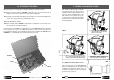
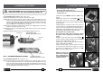
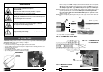
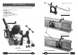
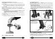
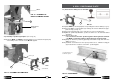
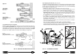
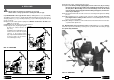

FIG. 6
FIG. 7
The spindle is advanced by moving the
lever (36) (See Fig. 6 a). The lever is fi t-
ted with a release pawl (39) which, when
pressed, renders it independent of the
hub and hence the spindle; the opera-
tor can therefore easily vary the angular
position of the lever without movement of
the spindle (Fig.6).
6c - With the hub released, moving the lever
towards the operator produces a cor-
responding advance of this spindle.
6a - Moving the lever (36) towards the
operator produces a corresponding
advance of the spindle.
5.1) Adjustment of the advance lever
The movement of the lever must never be
loose, for adjustment proceed to tighten it by
loading the cup springs by means of the as-
sociated self-locking nut, after removing the
protective cap (see Fig. 7).
6b - With the release pawl (39) pressed, the le
ver is released from its hub and can repeat
the previous travel without the spindle moving.
36
25 10
LD-41P
VAL MPA
VAL LD
When work has been completed, put away the drill by proceeding as follows:
12.1) Depressurise the tank of the SR5000 cooling unit (see § 4), close the tap (02) on
the tube from the tank, and disconnect the quick-coupling (03).
12.2) Carefully clean the drill, particularly in the spindle area, removing machining waste
(swarf, etc.) and any deposits of lubricating coolant.
12.3) Fully withdraw the spindle.
12.4) Place the drill and the SR5000 cooling unit in a sealed place free from dust, mois-
ture and the risk of accidental impact.
For better protection
Cembre
recommends the use of the VAL LD metal case designed
for this purpose (see § 3.2). The DBG-F2 moving arm device allows the drill to be
housed and locked in the case. A suitable housing is also provided in this VAL LD for the
VAL MPA case containing the most commonly used accessories.
12. STORING THE DRILL
5. SPINDLE ADVANCE LEVER