
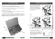
Specifications


07
18
Guide bit PP...
Guide bit PPL ...
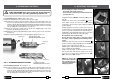
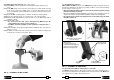
STOP THE ENGINE when servicing the drill: before removing
the broach cutters, spiral bits, positioning templates etc.
6.1) Assembling broach cutters (Ref. to Figs. 8-11).
6.1.1) Insert the guide bit in the cutter from the side of the spigot.
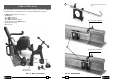
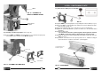
6.1.2) Using the lever (36), position the spindle shaft (07) so that both grub screws (18)
become accessible and suffi cient space is provided to insert the cutter; if necessary
rotate the spindle shaft manually and suffi ciently by inserting the 4 mm male hexagon
key in the appropriate intermediate gear housing (33) in the crankcase of the drill
corresponding to the feed handle (71) (see Fig. 11).
6.1.3) Insert the cutter in the spindle shaft so that the two engaging dogs on the cutter
spigot line up with the grub screws (18).
6.1.4) Clamp the cutter by fully tightening the grub screws by means of the 4 mm male
hexagon key.
6.1.5) Check that the guide bit slides freely by applying slight pressure on it.
6.2) Assembling spiral bits (Ref. to Figs. 9 - 11)
6.2.1) Using the advance lever, position the spindle shaft so that both grub screws be-
come accessible and suffi cient space is provided to insert the spiral bit; if necessary
rotate the spindle shaft manually and suffi ciently by inserting the 4 mm male hexa-
gon key in the appropriate intermediate gear housing in the crankcase of the drill
corresponding to the feed handle (see Fig. 11).
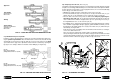
FIG. 8 – ASSEMBLING BROACH CUTTERS
Short type broach cutter
Maximum drilling thickness: 25 mm
Long type broach cutter
Maximum drilling thickness: 50 mm
Engaging dogs
11 24
a)
b)
e)
c)
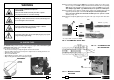
NOTE: the engine will
perform at its optimum
after a "running-in" peri-
od of approximately 200
drilling operations.
d)
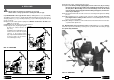
Before starting the engine, ensure that:
- the spindle shaft is fully retracted.
- the accelerator control lever is positioned at the low
speed position "0".
11.1) Set the engine "ON/OFF" switch to the "ON" position
(Fig. a).
11.2) Set the choke lever to the CLOSED position;
when engine is warm or in the case of high ambient
temperatures, this lever may require setting to the OPEN
position (Fig. b).
11.3) Keeping the accelerator control lever at the low
speed position, press the priming bulb repeatedly until fuel
can be seen in the clear-plastic fuel-return tube (Fig. c).
11.4) Pull the starter grip lightly until resistance is felt, then
pull briskly (Fig. d). Return the starter grip gently.
Do not pull the rope out all the way.
Do not allow the starter grip to snap back against
the engine, return it gently to prevent damage to the
starter.
11.5) If the choke lever was moved to the CLOSED
position to start the engine, gradually move it to the OPEN
position as the engine warms up (Fig. e).
11.6) Keep the engine “warming up” for at least 3 minutes
before starting any actual drilling.
11.7) To stop the engine, set the accelerator lever at the
low speed position and allow the engine to run at low
speed for 2 or 3 minutes before stopping. Set the "ON/
OFF" switch to the "OFF" position.
11. STARTING THE ENGINE
6. PREPARING THE DRILL