$7.50 Installation, Operation, and Maintenance Manual CEMLINE CORPORATION® Electric Water Heaters (Series EHB & FTB) and Electric Water & Steam Boilers EHB Series Water Heaters FTB SeriesWater Heaters Water and Steam Boilers CEMLINE CORPORATION P. O. Box 55, Cheswick, PA, 15024 Phone: (724) 274-5430 • FAX (724) 274-5448 www.cemline.
Table of Contents Section Page Disclaimers ..........................................................................................................................1 General Information.............................................................................................................2 Power Requirements ................................................................................................2 Construction....................................................................................
Maintenance - Electric Water Heaters and Boilers............................................................29 Electric Power Connections - Rewiring and Reconnecting...................................29 Thermostats (Operating, Auxiliary High Temperature Limit, and High Temperature Limit) - Resetting and Replacement......................................30 Contactor - Replacement .......................................................................................33 Fuses - Inspection and Replacement.......
Disclaimers This Installation, Operation, and Maintenance Manual is intended to be as complete and up to date as possible. It covers the installation, operation, and maintenance procedures for CEMLINE CORPORATION's Electric Water Heaters (FTB & EHB Series) and Electric Water and Steam Boilers. CEMLINE reserves the right to update this manual and other product information concerning installation, operation, and / or maintenance, at any time and without obligation to notify product owners of such changes.
General Information This Installation, Operation, and Maintenance Manual is designed as a procedural guide for all CEMLINE CORPORATION Electric Water Heaters and Boilers. Covered in this manual are: v EHB Series Vertical and Horizontal Electric Water Heaters; v FTB Series Vertical and Horizontal Electric Water Heaters; and v Vertical and Horizontal Electric Water and Steam Boilers.
For Controls All CEMLINE Electric Water Heaters and Boilers use 120 volts for control operation. Whether 208, 240, 415, or 480 volts are utilized to heat water, the application line voltage is connected to an isolation transformer that provides constant 120 volt control power. Construction All CEMLINE Electric Water Heaters and Boilers are constructed from superior materials and incorporate only the highest quality components.
Electric Water Heater and Boiler Jackets The jackets used for all CEMLINE Electric Water Heaters and Boilers are equipped with steel jackets that are professionally coated with a superior quality enamel paint. This procedure increases corrosion resistance and provides an attractive, easy to maintain surface. A nameplate, mounted to the jacket, bears the model and serial numbers of the unit. These identification numbers should be included in all correspondence regarding the unit.
Other Components All other components, included in CEMLINE Electric Water Heaters and Boilers, have been specifically selected to meet the individual design specifications of the unit. Each component is judged to be of the highest quality to provide long life and superior performance.
Advantages and Benefits of CEMLINE Electric Water Heaters and Boilers v STONESTEEL® tanks offer years of reliable, trouble free service. v Highest quality design, construction, and components. v Built and "Packaged" to meet exact customer design specifications. v CEMLINE "Packaging" helps keep installation time to a minimum. v Offers a wide range of configurations and capacities. v Configured to utilize 208, 240, 415, or 480 volts for heating water.
To order replacement parts, contact CEMLINE CORPORATION at the address listed above, or call toll free: USA Phone: (800) 245-6268 Note: Please include the model and serial number of the unit for which the parts are being ordered. If ordering by phone, please have this information readily available.
General Notes and Warnings Notes v This manual is intended to cover installation, operation, and maintenance procedures for CEMLINE CORPORATION Electric Water Heaters and Boilers. Since each unit is built to meet customer specifications, instructions may, at times, seem general in nature. Where procedures differ substantially between Series EHB and FTB Water Heater, or Electric Water and Steam Boilers, specific notes will be given.
v 1. Turn off and lock out the electric power supply to the unit in an approved manner. 2. Turn off the cold water inlet and hot water outlet valves. 3. Contact in-house maintenance personnel or CEMLINE CORPORATION for instructions. For all piping connections, the use and / or type of joint compound or sealer on each joint should be determined by referring to local codes, accepted standards, and / or the requirements of the installing contractor.
3. t t all joints between low water cut off control, gauges, valves, etc. Before attempting any installation, operation, or maintenance procedures pertaining to the unit: 1. assure that the electric power supply has been turned off and locked out in an approved manner; 2. if the unit has been in operation, allow the water in the tank, as well as all components and surfaces (heating elements, hot water outlet lines, etc.) to cool before starting the procedure; 3.
Product Features and Specifications Congratulations on purchasing a CEMLINE CORPORATION Electric Water Heater or Boiler. The unit purchased will offer years of superior dependable service. CEMLINE Electric Water Heaters and Boilers are one of the most economical methods of furnishing hot water or boiler water because of the superior design of the tanks and heating elements. All CEMLINE Electric Water Heaters and Boilers are "Packaged" and ready for installation.
Installation Transporting and Unpacking the Unit Most CEMLINE CORPORATION Electric Water Heaters and Boilers Generators are crated, as necessary, at the factory. The crating is designed to provide protection for the unit during transportation, and to provide a safe means by which to lift and move the unit with a fork lift or hand truck. Larger horizontal units are shipped uncrated, but fitted with lifting lugs attached to the tank to provide a safe means for lifting and moving the unit.
In areas prone to seismic activity, it is recommended that the unit be mounted to the floor, according to recommended procedures for the site, to make the units less susceptible to seismic damage. Familiarization with the Unit and Components CEMLINE Electric Water Heaters and Boilers are designed to make installation a relatively simple procedure. Because the unit is "Packaged," after placing and mounting the unit, installation involves: 1. connecting the cold water source to the cold water inlet; 2.
Note: Some Electric Steam Boilers are equipped with water feeder or pump. If so, the shutoff valve must be installed upstream from the water feeder or pump. The shutoff valve should be in the closed position and remain so until the installation is complete. Note: For all piping connections, the use and / or type of joint compound or sealer on the joint should be determined by referring to local codes, accepted practices, or the requirements of the installing contractor.
The CEMLINE Electric Water Heaters and Boilers have been completely wired during assembly. Connecting the electric power supply to the unit consists simply of connecting the correct voltage, phase, and amperage power leads to the terminal strip or circuit breaker. The exact voltage, phase, and amperage requirements for the unit can be determined from the rating plate affixed to the jacket of the unit, or from the Submittal Sheet and Wiring Diagrams supplied with the unit.
Electric Steam Boilers For Electric Steam Boilers, the relief valve should be vented to atmosphere (generally through the roof). The piping used in the vent system must be of adequate size to handle the capacity of the pressure relief valve and vent. The vent piping system should incorporate a "drip pan elbow" to allow for condensate drainage. The drip pan elbow should be piped to a to a suitable drain.
Operation After all installation procedures have been completed, all power connections and cold water, hot water, and relief piping joints have been double checked, the unit is ready for operation. As a precaution, it is strongly suggested that the following startup and shutdown procedures be followed. Startup Procedures 1. Assure that all manual shutoff valves on cold water and hot water lines are closed. t The combination of electricity and water can pose a very dangerous situation.
The auxiliary thermostat should be set ten degrees (10°) above the temperature at which the individual thermostats are set. Each unit is equipped with one auxiliary high temperature thermostat that is recognizable by the red dial. The high limit thermostat is factory preset at 205 degrees (205°) and is not user adjustable. 3. Slowly open the manual shutoff valve on the cold water inlet line, checking to assure that there are no leaks at the valve or any joints.
If all pilot lights are illuminated, the system has adequate water and is functioning within the high temperature limit. 8. After approximately thirty (30) minutes of operation, shut off and lock out the power and feel each wire connection and fuse clip for excessive temperature. If any connection or clip is found to be excessively hot, check to assure the integrity of the connection. All connections must be tight for proper operation. 9. Close and lock the door to the electric control cabinet. 10.
that all pilot lights are illuminated. If any pilot light is not illuminated, it means that a problem exists that should be investigated. Daily Operation - Electric Steam Boilers CEMLINE Electric Steam Boilers are equipped with a gauge glass and water feeder or pump to insure proper water level within the unit. The water level within the unit should be checked, via the gauge glass, at least twice a day.
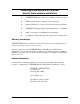
Parts List Replaceable Parts List The following is a list of parts that are generally replaceable, by trained / certified personnel, on CEMLINE CORPORATION Electric Water Heaters and Boilers. The replaceable parts may vary, depending on the unit and the particular design specifications to which the unit was constructed. If there are questions concerning the replaceable parts for the unit, refer to the original design specifications, or contact CEMLINE CORPORATION.
CEMLINE Electric Boilers Only Contactor Coils Gauge Glass High Pressure Cut Off (Automatic Reset - Steam Only) High Pressure Cut Off (Manual Reset - Steam Only) High Temperature Limit Thermostat (Manual Reset) Adjustable High Temperature Limit Thermostat (Automatic Reset) Pump Controller (Some Steam Boilers Only) Step Controller - Solid State Mother Board Black Card White Card(s) Green Card Yellow Card Potentiometer Step Controller Thermistor Water Feeder (Some Steam Boilers Only) Suggested Spare Parts For
Ordering Information All replacement parts for CEMLINE Electric Water Heaters and Boilers can be ordered directly from: CEMLINE CORPORATION P. O. Box 55 Cheswick, PA 15024 Phone: (800) 245-6268 Fax: (724) 274-5448 Note: Replacement parts can also be ordered through your authorized sales agent. Please include the model and serial number of the unit for which the parts are being ordered. If ordering by phone, please have this information readily available.
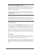
Inspection The following table summarizes the recommended time intervals for inspections of the Electric Water Heaters and Boilers, components, and electrical system.
Recommended Inspections Electric Boilers Only Time Interval To Be Inspected Contactor Coils Gauge Glass (Steam Boilers Only) High Pressure Cut Off Potentiometer Pump (Steam Boilers Only Some Models) Step Controller Step Controller Thermistor Water Feeder (Steam Boilers Only - Some Models) Per Manu. Specs.
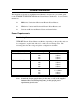
Troubleshooting The following table summarizes problems that may be encountered over the life of CEMLINE CORPORATION Electric Water Heaters and Boilers, and the procedures to remedy those problems. The left-hand column lists the symptoms. The remaining columns are suggested procedures or "remedies" that should be followed to identify and correct the problem. If a "ü " appears in a remedy column, the corresponding procedure(s) should be followed to identify and correct the problem.
2. The thermostat(s) are not correctly sensing the water temperature. n 3. A fuse(s) has "blown". n 4. Check all lines and joints for signs of leakage. Repair any leaks that are found. The inlet, outlet, or pressure / temperature relief lines are not properly piped. n 10. Reduce the water pressure entering the unit. A leak exists in the inlet or outlet lines, or at one of the joints. n 9. Replace the pressure / temperature relief valve.
n 11. Check and replace the water feeder or pump controller if found to be defective. (Reference the water feeder and pump controller replacement procedure on page 58) The solid state step controller or thermistor (probe) is malfunctioning. n Check and replace the step controller (or internal boards) and thermistor if found to be defective. (Reference the step controller and board replacement procedure on page 53; reference the step controller thermistor replacement procedure on page 56.
Maintenance - Electric Water Heaters and Boilers The information contained in this section details service and maintenance procedures for the inspection and replacement of the components of CEMLINE Electric Water Heaters and Boilers. Remember, this manual serves all CEMLINE Electric Water Heaters and Boilers. Therefore, the maintenance procedures may be general in some instances. Where there is a dramatic difference between the procedures pertaining to water heaters and boilers, it will be noted.
2. Unlock and open the door to the electric control cabinet. 3. After assuring the power has been turned off, disconnect and rewire the electrical connections in question. 4. Turn the power on and check that the component(s) that has been rewired is functioning properly. 5. Follow the startup procedure on page 17 of this manual to return the unit to operation.
The auxiliary high temperature limit thermostat will also "trip" when the water temperature surpasses the temperature set on the thermostat. However, the auxiliary high temperature limit thermostat will reset automatically when the water temperature drops below the set temperature. Replacement If any of the thermostats are found to be malfunctioning and need to be replaced, follow the procedures detailed below. 1.
in the compression fitting, as well as the temperature probe will come out of the tank with the compression fitting body. 8. Remove the body of the thermostat from its mounting. 9. Verify that the new thermostat is rated the same as the thermostat that is being replaced. 10. Mount the new thermostat, being careful not to damage the capillary tube or temperature probe. 11. Carefully configure (bend) the capillary tube to allow the temperature probe to be inserted into the tank.
limit thermostat should be set ten degrees (10º) higher then the operating thermostats. 18. Refill the tank with water, examining the tank, compression fitting, and capillary tube for any signs of leakage. 19. If no leakage is detected, reposition any fiberglass insulation that was moved to provide access to the compression fitting. 20. Follow the start up procedures on page 17 to return the unit to operation.
Fuses - Inspection and Replacement 1. Turn off the power to the unit. t The combination of electricity and water can pose a very dangerous situation. Assure that all power has been shut off / disconnected and locked out in an approved manner, before attempting any installation or maintenance procedures. 2. After assuring that the power has been turned off and locked out, unlock and open the door to the electric control cabinet.
2. After assuring that the power is turned off and locked out, and the tank has been drained and given a chance to cool, unlock and open the door to the electric control cabinet. Note: Figure 1 illustrates the typical EHB type heating element and mounting. 3. Disconnect the electrical connections at the terminals of the heating element to be replaced. It is suggested that the wires be tagged to assure correct reconnection. 4.
8. A new gasket has been supplied with the replacement heating element. Slide the new gasket over the heating element and align it with the face plate. Follow recommendations contained in the manufacturer's documentation, local codes, or accepted contractor practices as to the use and / or type of joint compound or sealer on the gasket and flange surfaces. 9. Insert the element into the tank. Be sure it has been installed with arrows, that appear on the element, pointing in correct directions. 10.
2. After assuring that the power is turned off and locked out, and the tank has been completely drained and given a chance to cool, unlock and open the door to the electric control cabinet. 3. Remove the cover from the heating element. Note: Figures 2 and 3 illustrate the typical FTB type heating element and mounting. 4.
Figure 2: Detailed Drawing of Typical FTB Type Heating Element Figure 3: Detailed Drawing of Typical FTB Type Heating Element Mounting 38
10. Each rod is soldered to the element spacers. Unsolder and pull the rods out of the spacers. 11. Remove the compression fitting body. Note: When changing a rod, always replace the body, sleeve, ring, and cap nut of the compression fittings. 12. Thoroughly clean the flange of the heating element to remove any particles of gasket or sealer that remain. This will help assure a proper seal when the new / repaired heating element and gasket are mounted. 13.
Note: Bolts used to secure the FTB type heating element assembly in CEMLINE Electric Water Heaters and Boilers are rated as either Grade A or Grade 5. Grade A bolts have no marking on the head. Grade 5 bolts are designated by three (3) slash marks on the head (///). a. Lubricate the bolt threads and the nut faces with a suitable lubricant. b. Insert the bolts through the flanges, then start the nuts. c. Number all bolts so that torquing requirements can be followed.
.062" Ring Gaskets Nominal Pipe Size (IN) 3" 4" 5" 6" 8" 10" 12" 14" 16" t Garlock Bolt Torque Values Grade 5 Bolts ANSI - 300# Flanges Number of Bolts Size of Bolts (IN) 3/4" 3/4" 3/4" 3/4" 7/8" 1" 1 1/8" 1 1/8" 1 1/4" 8 8 8 12 12 16 16 20 20 Grade 5 Target Torque (FT - LBS) 160 160 160 160 256 392 568 521 730 Be sure of the bolt grade used in the unit. Do not tighten a Grade 5 bolt to the torque specification of a Grade A bolt, or vise versa.
26. After checking to make sure all tools / foreign matter has been removed from the electric control cabinet, and that all personnel are clear, turn on the power while visually checking for any "arcing" or sparking at the refitted electric leads. 27. If no evidence of arcing is detected, replace the heating element cover and close and lock the door to the electric control cabinet. The unit is now back in service.
Float Type Low Water Cut Off Control - Replacement The float type low water cut off control assures that if the water level in the tank drops to an unsafe level, power will be cut off so that the heating elements will not "burn out". If the low water cut off is determined to be defective and must be replaced, follow the detailed procedures below. 1. Follow Steps 1 through 5 of the shutdown procedure (page 19) to take the unit off-line before attempting to replace the low water cut off control.
10. As the unit is filling and heating, inspect the joints at the low water cut off control (and any joints of other components that were loosened) for signs of leakage. Probe Type Low Water Cut Off Control - Replacement The probe type low water cut off control assures that if the water level in the tank drops to an unsafe level, power will be cut off so that the heating elements will not "burn out".
Pressure / Temperature Relief Valve Replacement If the pressure or pressure and temperature relief valve mounted on the tank is not functioning correctly and must be replaced, follow the procedures outlined below. 1. Follow Steps 1 through 5 of the shutdown procedure (page 19) to take the unit off-line before attempting to replace the pressure gauge. t The combination of electricity and water can pose a very dangerous situation.
2. After assuring that the power has been turned off and locked out, the pressure has been bled from the tank, the water has been drained, and the unit has cooled, carefully disconnect the small line connecting the pressure gauge with the tank. This line should only be disconnected at the gauge. 3. Remove the gauge from its mounting. 4. Mount the new gauge. 5. Reconnect the small line to the gauge.
On / Off Switch - Replacement If the on / off switch is determined to be defective and must be replaced, follow the procedures outlined below. 1. Turn off the power to the unit. t The combination of electricity and water can pose a very dangerous situation. Assure that all power has been shut off / disconnected and locked out in an approved manner, before attempting any installation or maintenance procedures. 2.
1. Turn off the power to the unit. t The combination of electricity and water can pose a very dangerous situation. Assure that all power has been shut off / disconnected and locked out in an approved manner, before attempting any installation or maintenance procedures. 2. After assuring that the power has been turned off and locked out, access the rear of the pilot light and tag the connected wires to assure correct reconnection after the new light is installed. Remove the wires. 3.
6. To install the new breaker, insert the side with the wire terminals in the receptacle first, and then push in on the opposite side until completely seated. 7. Reconnect the wires in the same position from which they were removed from the original circuit breaker. 8. After assuring that all tools and foreign materials have been removed from the electric control cabinet, and that all personnel are clear of the unit, turn on the power. As the power is turned on, visually inspect for signs of "arcing".
Maintenance - Electric Boilers Only The procedures contained in this section are for components that are only supplied with CEMLINE Electric Water and Steam Boilers. Maintenance procedures for components that are not specific to Electric Boilers are contained in the previous section. Contactor Coils - Replacement If a contactor coil is determined to be defective and must be replaced, follow the procedures outlined below. 1. Turn off and lock out the power to the unit.
Gauge Glass - Replacement (Electric Steam Boilers Only) 1. Follow Steps 1 through 4 of the shutdown procedure (page 19) to take the unit off-line before attempting to replace the gauge glass assembly. t The combination of electricity and water can pose a very dangerous situation. Assure that all power has been shut off / disconnected and locked out in an approved manner, before attempting any installation or maintenance procedures. 2.
Resetting of the High Pressure Cut Off Switch (Manual Reset) If the pressure in the unit surpasses the limit set by the manual reset high pressure cut off switch, the switch will "trip" and shut down the unit. To reset the high pressure cut off switch, after the cause of the excessive pressure problem is identified and corrected, follow the procedures listed below. 1. Locate the high pressure cut off switch. 2. Depress and release the red button to reset the switch.
documentation, local codes, or accepted contractor practices as to the use and / or type of joint compound or sealer at the connections. 8. Tighten the body of the switch with the correct size wrench. 9. Reconnect the wires to the new switch, checking to assure that they are attached in the same position from which they were removed. 10. Refill the tank with water, examining the joint between the switch and tank for any signs of leakage. 11.
2. Locate the box housing the solid state step controller mounted on the exterior of the boiler. Remove the cover. 3. If a specific board has been determined to be defective, locate the board and remove it from its seat by pulling gently away from the step controller. 4. Each board can be reseated in the appropriate mother board receptacle by simply aligning the board and gently pushing the board into place. 5.
14. If no arcing is detected, the unit is ready for operation. Potentiometer - Replacement The potentiometer is mounted on the box that houses the solid state step controller and is mounted on the door of the solid state step controller panel. If it is determined to be bad and must be replaced, follow the steps. t Solid state component boards are very fragile and subject to damage from any type of electrical charge - even static electricity.
11. If no arcing is detected, the unit is ready for operation. Solid State Step Controller Thermistor - Replacement The solid state step controller thermistor is connected by wire to the step controller, and via compression fitting to the tank. It is accessible through the electric control cabinet. If the thermistor is found to be malfunctioning and needs to be replaced, follow the procedures detailed below.
Note: Do not remove the compression fitting cap nut. This could allow the thermistor to become free and possibly fall into the tank. 7. Using the correct size six (6) point socket, remove the body of the compression fitting from the tank. The remainder of the wires, still in the compression fitting, as well as the thermistor will come out of the tank with the compression fitting body. 8. Verify that the new thermistor is rated the same as the one that is being replaced. 9.
Water Feeder or Pump Controller - Replacement (Electric Steam Boilers Only) The water feeder or pump controller is integrated into the piping on the side of Electric Steam Boilers. It is located no less then two inches (2") above the highest heating element in the unit. If the water feeder or pump controller is determined to be defective, follow the steps below to replace the component. 1.
9. If no leaks are found, follow the startup procedures (page 17) to put the unit back on-line.
Appendix A Typical Wiring Diagrams Figure A-1: Typical Wiring Diagram For Electric Water Heaters 60
Appendix A (cont'd) Figure A-2: Typical Wiring Diagram For Electric Water Boilers 61
Appendix A (cont'd) Figure A-3: Typical Wiring Diagram For Electric Steam Boilers 62
Appendix B Bolt Torque Procedure SEQUENTIAL ORDER 1 3 5 7 - 2 4 6 8 ROTATIONAL ORDER 1 5 3 7 2 6 4 8 8-BOLTS SEQUENTIAL ORDER 1 3 5 7 9 11 12-BOLTS 63 - 2 4 6 8 10 12 ROTATIONAL ORDER 1 5 9 3 7 11 2 6 10 4 8 12
Appendix B (cont'd) Bolt Torque Procedure SEQUENTIAL ORDER 1 3 5 7 9 11 13 15 - 2 4 6 8 10 12 14 16 16-BOLTS SEQUENTIAL ORDER 1 3 5 7 9 11 13 15 17 19 20-BOLTS 64 - 2 4 6 8 10 12 14 16 18 20 ROTATIONAL ORDER 1 9 5 13 3 11 7 15 2 10 6 14 4 12 8 16 ROTATIONAL ORDER 1 13 5 17 9 3 15 7 19 11 2 14 6 18 10 4 16 8 20 12
65