
Installation Guide


19
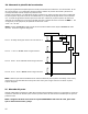
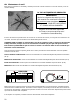
Step One:
Pilot holes must be drilled rst. To do this, use a fence bracket
as a guide and mark the center point for pilot hole locations as
shown in Illustration A. Using a 3/8” drill bit, drill pilot
holes for all Termination Bracket locations.
Step Two:
Measure back approximately 2-1/2” - 4” on the rail as
shown in Illustration B and then bend the rail back as
shown in Illustration C.
Step Three:
Insert the bent piece of rail into the slot on the Termination
Bracket as shown in Illustration D. Make sure the short side
of the bent rail is farthest from the mounting hole in the
bracket. Once the rail is inserted, slide the provided
bent pin into place as shown in the illustration.
Step Four:
Attach the Termination Bracket using the supplied lag screw (A)
and washer (B) as shown in Illustration E. Once the bracket is
attached to the post, tension the rail from the opposite end to
take up slack.
NOTE: Do NOT overtighten the lag screw. Termination
Bracket should t snug to post, but still be able to move
with slight pressure.
A
B
D
E
C
2
1/2
” 4”
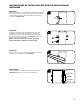
Opción 3: Bucle de Terminación
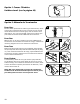
Opción 4: Ménsula en T
Paso Uno:
Deslice el carril a través del bucle y pliegue 3’’ a 4” de carril,
como se muestra.
Paso Dos:
Envuelva el carril alrededor del poste y deslice la parte plegada
del carril en el bucle.
Paso Tres:
Instale una ménsula de CenFlex como se muestra y ejerza
tensión en el carril para ajustar al poste.
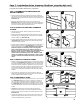
Paso Uno:
Retire la ménsula existente de la cerca si es necesario y
coloque la Ménsula en T sobre el carril como se muestra en
la Ilustración A. Use la ménsula en T como plantilla para
marcar las ubicaciones de los orificios. Usando una broca de
¼", perfore orificios guía para todas las ubicaciones de las
ménsulas en T.
Paso Dos:
Sujete la Ménsula en T usando los tornillos de compresión
provistos como muestra la Ilustración B.
Paso Tres:
Mida aproximadamente entre 2-1/2” y 4” en el carril, como se
muestra en la Ilustración C y luego pliegue el carril, como se
muestra en la Ilustración D.
Paso Cuatro:
Inserte la parte plegada del carril en la ranura de la Ménsula
en T como se muestra en la Ilustración E. Si es posible,
disponga el lado corto del carril plegado entre la ménsula y el
carril. Una vez que se inserta el carril, deslice la clavija doblada
proporcionada en su lugar, como se muestra en la ilustración.
Tense el carril desde el extremo contrario para eliminar la
distensión.
NOTA: se requiere un ensamble de apuntalamiento
horizontal/diagonal para evitar que se mueva el poste
del extremo cuando se aplica tensión. Refiérase al
paso 2 para las instrucciones acerca de ensamble de
apuntalamiento (página 36)
Step One:
Remove existing fence bracket if needed and place T-Bracket
Attach the T-Bracket using the supplied lag screws as in
Illustration B.
over rail as shown in Illustration A. Use the T-Bracket as a
template to mark hole locations. Using a 1/4” drill bit, drill pilot
holes for all T-Bracket locations.
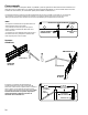
Step Two:
Measure back approximately 2-1/2” - 4” on the rail as shown in
Illustration C and then bend the rail back as shown in
Illustration D.
Step Three:
Insert the bent piece of rail into the slot on the T-Bracket as
shown in Illustration E . If possible, have the short side of the
bent rail between the bracket and the rail. Once the rail is
inserted, slide the provided bent pin into place as shown in the
illustration. Tension the rail from the opposite end to take up
slack.
Step Four:
NOTE: A horizontal/diagonal brace assembly is required to
prevent end post from moving when tension is applied. Refer to
Step 2 for bracing assembly instructions (page 10).
A
C
B
D
2
1/2
” 4”
E
Step One:
Slide rail through loop and bend back 3”- 4” of rail as shown.
Wrap rail around postand slide bent portion of rail into loop.
Step Two:
Install a CenFlex bracket as shown and pull tension on rail
to pull up tight to post.
Step Three:
B C
2
1/2
” 4”