50 TON AIR/HYDRAULIC BOTTLE JACK Model 97548 Set up And Operating Instructions Diagrams within this manual may not be drawn proportionally. Due to continuing improvements, actual product may differ slightly from the product described herein. Distributed exclusively by Harbor Freight Tools®. 3491 Mission Oaks Blvd., Camarillo, CA 93011 Visit our website at: http://www.harborfreight.com Read this material before using this product. Failure to do so can result in serious injury. Save this manual.
Save This Manual NOTICE is used to address practices not related to personal injury. Notice Keep this manual for the safety warnings and precautions, assembly, operating, inspection, maintenance and cleaning procedures. Write the product’s serial number in the back of the manual near the assembly diagram (or month and year of purchase if product has no number). Keep this manual and the receipt in a safe and dry place for future reference.
goggles. Safety equipment such as non-skid safety shoes, hard hat, or hearing protection used for appropriate conditions will reduce personal injuries. unfamiliar with the tool or these instructions to operate this tool. Tools are dangerous in the hands of untrained users. e. Maintain this tool. Check for misalignment or binding of moving parts, breakage of parts and any other condition that may affect the tool’s operation. If damaged, have the tool repaired before use.
. Bleed the hydraulic system of the Bottle Jack before its initial use. 5. Always place the Bottle Jack on a dry, oil/grease free, solid, level floor surface capable of supporting the weight of the Jack and all other additional tools and accessories. 6. Apply the vehicle’s parking brake and chock the tires before lifting the vehicle. 7. Lift the vehicle only by the manufacturer-recommended lifting points. 8. Stay out from under the load while it is being lifted or supported. 9.
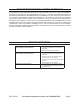
Specifications Maximum Lifting Capacity 50 Tons (100,000 pounds) Required Air Pressure 110-120 PSI Air Inlet Fitting 1/4" - 18 NPT Minimum Height 12" Maximum Height 19" Ram Travel 7" Net Weight 89.70 lbs Air Hose Length 46" Jack Handle 20"L (2 pcs, upper & lower) Unpacking When unpacking, check to make sure that the item is intact and undamaged. If any parts are missing or broken, please call Harbor Freight Tools at the number shown on the cover of this manual as soon as possible.
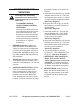
Plug (15); and wipe the jack’s exterior. (See Assy. Diagram.) f. IMPORTANT: After bleeding the Bottle Jack, make sure to test the unit to ensure it operates properly. g. NOTE: To prevent damage to the Bottle Jack, check for excessive air and/or low hydraulic oil regularly. Note: There are threaded holes on sides of Jack base, which are predrilled for the mounting of an optional wheel and handle kit (not included). Contact Harbor Freight Tools for details on this optional kit. (See below photo). 4.
lifting. (See Assy. Diagrams.) d. To lift the vehicle, continue to depress the Lever on the Air Valve assembly (32). Once the vehicle is lifted, make sure to place the Lock Lever in its locked position. (See Assy. Diagrams.) 5. Once the vehicle is raised, slide a jack stand (not included) to the proper lifting point referred to in the vehicle manufacturer’s manual. If using two jack stands, make sure they are on the same point on each side of the vehicle.
Maintenance And Servicing its hydraulic system of excessive air. To do so: a. Insert the Lower Handle (41) onto the Release Valve Screw (4). Then turn the Release Valve Screw 1-1/2 turns counterclockwise releasing pressure. (See Assy. Diagram.) Procedures not specifically explained in this manual must be performed only by a qualified technician. b. Remove the Filler Plug (15), and fill the Reservoir (14) with hydraulic oil (not included). (See Assy. Diagram.
PLEASE READ THE FOLLOWING CAREFULLY The manufacturer and/or distributor has provided the parts list and assembly diagram in this manual as a reference tool only. Neither the manufacturer or distributor makes any representation or warranty of any kind to the buyer that he or she is qualified to make any repairs to the product, or that he or she is qualified to replace any parts of the product.
ASSEMBLY DIAGRAM - Entire Unit SKU 97548 For technical questions, please call 1-800-444-3353.
PARTS LIST - Entire Unit Part No Description Qty Part No Description Qty 1 Base 1 23 Spring 1 2 Ball 1 24 Screw 1 3 Seal 1 25 O-Ring 1 4 Release Valve 1 26 Screw 1 5 O-Ring 1 27 Spring 2 6 Cylinder 1 28 Screw 2 7 O-Ring 2 29 Washer 2 8 Cup Seal 1 30 Air Motor 1 9 Ram 1 31 Air Hose 1 10 Packing 1 32 Air Valve 1 11 Handle 2 33 Pump Cylinder 1 12 Pin 1 34 O-Ring 1 13 R-Pin 5 35 Nylon Ring 1 14 Reservoir 1 36 Back Up Ring 1
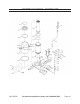
diagram - air motor SKU 97548 For technical questions, please call 1-800-444-3353.
PARTS LIST - air motor Part No Description Qty Part No Description Qty A01 Air Pump Cylinder 1 A25 O-Ring 1 A02 Nut 1 A26 Air Cylinder Cap 1 A03 Sealing Ring 1 A27 Bolt 4 A04 Nylon Ring 1 A28 Coupler Seat 1 A05 Copper Ring 1 A29 Retaining Ring 1 A06 Air Cylinder Seat 1 A30 O-Ring 2 A07 Nut 1 A31 Coupler 1 A08 Spring 1 A32 Air Hose 1 A09 Air Pump Piston 1 A33 Lock Lever 1 A10 O-Ring 2 A34 Lever 1 A11 Big Piston 1 A35 Nut 1 A12 Air Cylin
LIMITED 90 DAY WARRANTY Harbor Freight Tools Co. makes every effort to assure that its products meet high quality and durability standards, and warrants to the original purchaser that this product is free from defects in materials and workmanship for the period of 90 days from the date of purchase.