240 VOLT COMPRESSOR 4 HP PEAK – 29 GALLON Oil-lubricated Model 92504 ASSEMBLY AND OPERATING INSTRUCTIONS 3491 Mission Oaks Blvd., Camarillo, CA 93011 Visit our Web site at: http://www.harborfreight.com Copyright© 2005 by Harbor Freight Tools®. All rights reserved. No portion of this manual or any artwork contained herein may be reproduced in any shape or form without the express written consent of Harbor Freight Tools. For technical questions, please call 1-800-444-3353.
PRODUCT SPECIFICATIONS Motor 240 V~ / 60 Hz / Single Phase / 4 HP Peak / 3 HP Working / 3,400 RPM / 9 Load Amps / Two Capacitor (Run & Start) Overload Reset Button 15 Amp Power Cord 12 Gauge, 3-Wire (Stripped), 20 Ft. Long 240 Volt Power Cord Plug Not Included. Air Tank Capacity 29 Gallons CFM Airflow 16.4 @ 40 PSI / 15.7 @ 70 PSI / 14.5 @ 90 PSI / 13.
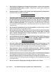
2. Do not operate compressors in explosive atmospheres, such as in the presence of flammable liquids, gases, or dust. Compressors create sparks which may ignite the dust or fumes. 3. Keep bystanders, children, and visitors away while operating a compressor. Provide barriers or shields as needed. ELECTRICAL SAFETY 1. Grounded compressors must be plugged into an outlet properly installed and grounded in accordance with all codes and ordinances.
6. Use safety equipment. Always wear eye protection. Make sure you are wearing your protective clothing, safety glasses with side shields and dust mask or air respirator, if appropriate. TOOL USE AND CARE 1. Do not force the compressor. Use the correct compressor for your application. The correct compressor will do the job better and safer at the rate for which it is designed. Never attempt to force the compressor to provide more pressure than it was designed for. 2.
SPECIFIC SAFETY RULES 1. CAUTION! Prior to its first use, and thereafter prior to each subsequent use, make sure to fill the Air Compressor with a premium quality, 30 weight, nondetergent oil to the specified level. Running the Air Compressor with no oil or with low oil will cause damage to the equipment and void its warranty. Refer to the “Operating Instructions” section for details on filling the Air Compressor with oil. 2.
parts when the unit is connected to electrical power. Always have compressor safety guards in place before turning compressor on. 13. Use approved air hose. Never use plastic or PVC pipe (unless specified for Air Compressors) to carry air under pressure. Regardless of its pressure rating, it can burst under pressure. Use only metal pipe. 14. Never plug the power cord of this product into an electrical outlet while standing on a wet or damp surface. 15.
SYMBOLOGY To extend the life of your air tools and equipment, we recommend installing an oiler and water filter in series with the Air Outlet Valves (4) of the Air Compressor. (See Figure C.) AIR COMPRESSOR TO TOOL OR EQUIPMENT OILER WATER FILTER FIGURE C ASSEMBLY INSTRUCTIONS To Attach A Power Cord Plug: The Power Cord (31) requires the attachment of a 240 volt, grounded, 3-Prong Plug (not included).
outlet that is properly grounded. To Attach Quick Connectors: Prior to use, the Air Compressor requires the attachment of a 1/4” NPT Quick Connector (not included) to each of its two Air Outlet Valves (4). To do so, wrap approximately 4” of pipe thread sealant tape (not included) around the male threads of the Quick Connectors. Then, firmly screw the Quick Connectors into the Air Outlet Valves. (See Figure D.) To Fill The Air Compressor With Oil: 1.
3. Once the Oil Fill Cap (28) is removed, fill the Air Compressor with a premium quality, 30 weight, non-detergent oil until the level of the oil rises to the midway point in the Oil Level Indicator (35). Then, screw the Oil Fill Cap back onto the Oil Fill Hole. (See Figure D.) To Mount The Air Compressor: 1.
6. If using only one of the two Air Outlet Valves (4), attach an air hose (not included) to the Air Outlet Valve. Then, attach the other end of the air hose to the pneumatic tool that will be used. If using both Air Outlet Valves simultaneously, attach an air hose to each Air Outlet Valve. Then, attach the other ends of the air hoses to their respective pneumatic tools. (See Figure E.) To Start The Air Compressor: 1. Plug the Power Cord Plug (31) into the nearest 220 volt, grounded, electrical outlet.
5. Check to make sure the pneumatic tools that will be used are turned off and properly connected to their air hoses. 6. Once the Pressure Gauge (5) has reached at least 80 PSI, turn the Lever on the Air Outlet Valve (4) forward to its open position in order to supply air to the pneumatic tool. If both Air Outlet Valves are being used, turn both Levers forward to their open positions. (See Figure E.) 7.
To Turn Off The Air Compressor: 1. When finished using the Air Compressor, press down on its Power Switch (9) to turn off the unit. (See Figure E.) 2. Disconnect the Power Cord Plug (31) from its electrical outlet. 3. Turn on the pneumatic tools to expend all remaining compressed air from the Air Compressor, air hoses, and pneumatic tools. 4. Turn the Pressure Adjustment Knob (6) counterclockwise all the way to its “OFF” position. (See Figure E.) 5.
4. NOTE: Each time the Oil Fill Cap (28) is removed, observe the PCV Filter (41) that is located inside the Oil Fill Cap. When necessary, remove the PCV Filter and clean with a mild solvent. Allow the PCV Filter to dry. Then, replace the PCV Filter in the Oil Fill Cap, and screw the Oil Fill Cap back onto the oil fill hole. (See Figure F.) PCV FILTER (41) OIL FILL HOLE OIL FILL CAP (28) FIGURE F 5.
6. To replace the V-Belt: The Air Compressor is equipped with a V-Belt (size: A1168 Li). To replace the V-Belt, remove the four Nuts (24) and four Flat Washers (23) on the Outer Guard Screen (25). Next, remove the three Clips (34) located at the top of the Outer Guard Screen. Then, remove the Outer Guard Screen. (See Figure H.) CLIP (34) CLIP (34) OUTER GUARD SCREEN (25) LARGE V-BELT MOTOR BELT WHEEL (27) PULLEY (14) NUT (24) FLAT WASHER (23) NUT (24) FLAT WASHER (23) 7.
8. Remove the loose V-Belt (27) from the Large Belt Wheel and Motor Pulley (14). (See Figure H.) 9. Install a new V-Belt (27) on the Large Belt Wheel and Motor Pulley (14). (See Figure H.) 10. Slide the Motor (14) back toward its original position to tighten the tension on the V-Belt (27). NOTE: To determine the proper tension on the V-Belt, with your index finger press down on the V-Belt. The V-Belt should deflect downward about 3/4”.
PARTS LIST Part 1 2 3 4 5 6 7 8 9 10 11 12 13 14 15 16 17 18 19 20 21 Description Flat Washer (8) Screw (M8x16) Safety Release Valve Air Outlet Valve Pressure Gauge Pressure Adjustment Knob Connector Top Cover Power Switch Screw (M8x25) Spring Washer (8) Flat Washer (8) Nut (M8) Motor Tube Cap Ring Connector No Return Valve Exhaust Bracket Qty.
ASSEMBLY DIAGRAM 34 23/24 25 20 19 17 18 16 15 26 27 21/22/23/24 9 28/41 5 8 14 7 10/11/12/13 6 4 3 29 30 11/12/13 2 1 35 36/37/38/39 40 31 32 33 NOTE: Some parts are listed and shown for illustration purposes only, and are not available individually as replacement parts. SKU 92504 For technical questions, please call 1-800-444-3353.
WIRING DIAGRAM REV 05/06 SKU 92504 For technical questions, please call 1-800-444-3353.