
user manual


Page 10For technical questions, please call 1-800-444-3353.SKU 93785
10.25 x 1050
1725
=
6.24”
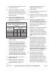
Or, use the following equation if you
have a 3450 RPM motor:
10.25 x 1050
3450
=
3.12”
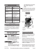
2. The 10-1/4 inch V-groove Belt Wheel
(35) of the Air Compressor Pump
must be in perfect alignment with the
motor pulley (not included).
Note: Ensure the Belt Wheel is installed
for counter-clockwise rotation when
facing the Belt Wheel side of the
Pump.
CAUTION: Misalignment between Motor
and Pump can damage the Belt
Wheel. Use a straight edge, such
as a yardstick, to check and adjust
alignment as needed.
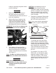
Verify that Belt Wheel turns freely 3.
where it overhangs mounting surface.
Place a V-groove belt (not included) 4.
over Belt Wheel (35) and motor pulley.
Pull Compressor Pump until properly 5.
aligned, and the belt is tight. Recheck
motor pulley, V-groove belt, and Belt
Wheel alignment.
Use a pencil to mark through the Air 6.
Compressor Pump mounting holes
onto the mounting surface.
Move Air Compressor Pump and drill 7.
four 3/8” holes in mounting surface.
Move the Air Compressor Pump back 8.
to its mounting position.
Secure each corner of base with 9.
a 3/8” diameter bolt, washer, lock
washer, and nut (all not supplied).
Mount the motor (not supplied) 10.
as recommended by the motor
manufacturer. Be sure that the motor
is securely mounted.
Make nal alignment and adjust 11.
belt tension with the motor. It may
be necessary to loosen the motor
mounting bolts to adjust the motor
location. To test the proper tension
on the V-belts, press down on the
belts, they should not depress more
than 1/2 inch at mid span. Tighten all
mounting hardware.
Push down on Belt Wheel with your 12.
hand and tighten the Belt Wheel bolt.
Connect plumbing hardware (not 13.
supplied) from the male ¾”- 14 TPI
Air Outlet (6) to the air destination
(i.e., air pressure tank, not supplied),
routing the tubing in the shortest
possible path.
Install a safety guard (not supplied) 14.
that surrounds the Motor Pulley,
V-belts, and Belt Wheel. This safety
guard must cover all sides of the
moving belts and pulleys. It should
have a clearance of about one inch
from the moving parts. The safety
guard must be sturdy enough to
prevent injury.
Note: A qualied electrician must wire in
a pressure switch control that turns
off motor when the pump reaches the
desired pressure (140 PSI or less).
Note: Always install Air Compressor Pump
to air tank that can withstand at least
140 PSI and has a safety valve.
Note: A high/low cut-in/cut-out switch
(not included) can be incorporated
to operate a motor starter or motor
REV 09j