
user manual


Page 9For technical questions, please call 1-800-444-3353.SKU 93785
hazard or exposing the power cord to
possible damage.
Assembly
Make sure that the inner faces of 1.
the wheel socket as well as the
Crankshaft (29) are clean and free of
burrs and roughness.
Apply a thin layer of grease to the 2.
interior of the socket and, with the
ridge end of the beltway pointing
towards the compressor, slide the
Belt Wheel (35) over the Crankshaft.
WARNING! Do not force or hammer the
Belt Wheel onto the Crankshaft.
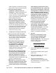
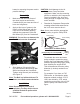
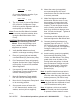
Bolt (32)
Washer
(34)
Figure 2
Wrench
(not included)
Belt Wheel (35)
3. Slide Washer (34) onto the Bolt
(32) and insert the Bolt through Belt
Wheel and thread into Crankshaft.
Tighten using Wrench (not included) -
See Figure 2.
Note: The Bolt is a left-hand thread. To
fasten, turn Bolt counterclockwise.
Installation.
Note: Depending on your level of
expertise, you may wish to have a
qualied technician perform this
installation.
CAUTION: Avoid damage to the Air
Compressor Pump and other
equipment. Make sure the mounting
surface on which the Air Compressor
Pump is installed is at, level and
strong enough to support the pump,
motor and tank.
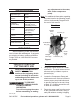
Place the Air Compressor Pump on the 1.
mounting surface at the same level as
the 3 HP motor used to drive it.
Note: Use a motor with the appropriate
size pulley to get the Pump RPM.
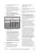
Calculation for Motor Pulley:
Motor Pulley
Pump Pulley
Pump Pulley Dia:
10.25”
(Pump Pulley Dia. x Pump RPM)
Motor RPM
10.25’ 1050
=
Motor
Pulley
Dia.
x
To calculate the motor and motor
pulley needed to power the pump,
multiply the Pump diameter (10.25”)
times the pump working RPM (1050),
then divide by the engine RPM.
This will determine the motor pulley
diameter (in inches) needed to run
the unit.
For example: If you have a 1725
RPM motor, to calculate the pulley
diameter needed, multiply 10.25 x
1050, then divide by 1725, which
equals the motor pulley size of 6.24”.
Use the pulley size closest to this
gure.
REV 09j