Complete Garage Air Kit 66747 Set up and Operating Instructions Distributed exclusively by Harbor Freight Tools®. 3491 Mission Oaks Blvd., Camarillo, CA 93011 Visit our website at: http://www.harborfreight.com Read this material before using this product. Failure to do so can result in serious injury. Save this manual. Copyright© 2009 by Harbor Freight Tools®. All rights reserved.
Save This Manual CAUTION, used with the safety alert symbol, indicates a hazardous situation which, if not avoided, could result in minor or moderate injury. Keep this manual for the safety warnings and precautions, assembly, operating, inspection, maintenance and cleaning procedures. Write the product’s serial number in the back of the manual near the assembly diagram (or month and year of purchase if product has no number). Keep this manual and the receipt in a safe and dry place for future reference.
b. c. Do not operate air compressor in explosive atmospheres, such as in the presence of flammable liquids, gases, or dust. The air compressor is able to create sparks resulting in the ignition of the dust or fumes. b. Stay alert. Watch what you are doing and use common sense when operating the tool. Do not use any tool while tired or under the influence of drugs, alcohol, or medication. A moment of inattention while operating the tool increases the risk of injury to persons. Dress properly.
persons. Any tool is dangerous in the hands of untrained users. f. g. h. Maintain any tool with care. Keep a cutting tool sharp and clean. A properly maintained tool, with sharp cutting edges reduces the risk of binding and is easier to control. Check for misalignment or binding of moving parts, breakage of parts, and any other condition that affects the tool’s operation. If damaged, have the tool serviced before using. Many accidents are caused by poorly maintained tools.
Symbol Definitions Symbol Property or statement WARNING marking concerning Risk of Hearing Loss. Wear hearing protection. WARNING marking concerning Risk of Respiratory Injury. Wear NIOSHapproved dust mask/respirator. WARNING marking concerning Risk of Explosion. Specific Safety Instructions 1. The warnings and precautions discussed in this manual cannot cover all possible conditions and situations that may occur.
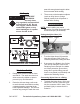
Functional Description Specifications Maximum Air Pressure 150 PSI Manifold Block Inlet Manifold Block Outlet 3/8” NPT 3/8” NPT Ball Valve 3/8” NPT The Water Drain Valve can be opened or closed to exhaust water from the Outlet Blocks. Turn the handle 90° parallel to valve to open, turn the handle 90° across to valve to close.
area with enough extra length to allow free movement while working. Air Supply To prevent explosion: Use only clean, dry, regulated, compressed air to power this air kit. Do not use oxygen, carbon dioxide, combustible gases, or any other bottled gas as a power source for this air kit. 3. There must not be hazardous objects (such as utility lines or foreign objects) nearby that will present a hazard while working.
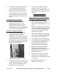
2. To remove the Nylon Hose (10) from any compression fitting in this kit, push in evenly on the release ring, and pull the Hose out of the fitting. 3. To reattach the Hose, trim the end of the Hose above the previous crimp, before attempting to reconnect to the fitting. Planning your air line layout. 1. Plan your air line layout before beginning. The air line can be installed inside the wall or on the surface of the wall.
Prepare Outlet Block (1) 1. Attach Straight Union connector (2) to each Outlet Block (1) as needed. Install Water Drain Valve (4) in bottom opening of Outlet Block. Insert a Brass Plug (7) into any unused openings in the Outlet Block. 2. Optionally, attach a 1/4” NPT quick release coupling (not included) to the 45° Elbow (6). 3. Attach the end of the Nylon Hose to the Straight Union (2). 4. Install the Outlet Blocks as desired.
3. 4. To prevent serious injury from accidental operation: Turn off any tool, detach the air supply, safely discharge any residual air pressure in the tool, and release the throttle and/or turn the switch to its off position before performing any inspection, maintenance, or cleaning procedures.
ASSEMBLY DIAGRAM 10 1 11 6 2 4 9 8 Part # 5 7 Parts LIST Description 3 Qt’y 1 Outlet Block 2 2 Straight Union (1/2” x 3/8” NPT) 6 3 Elbow Union (1/2”) 4 4 Ball Valve 2 5 Brass Nipple (1/4” NPT) 2 6 Brass 45° Elbow (1/4” NPT) 2 7 Brass Plug (3/8” NPT) 3 8 Compressor Manifold Block 1 9 Tee Fitting (1/2”) 2 10 Nylon Hose (100’ x 1/2”) 1 11 Cutting Tool (blade included) 1 REV 09g SKU 66747 For technical questions, please call 1-800-444-3353.
LIMITED 90 DAY WARRANTY Harbor Freight Tools Co. makes every effort to assure that its products meet high quality and durability standards, and warrants to the original purchaser that this product is free from defects in materials and workmanship for the period of 90 days from the date of purchase.