CENTRO 3900S Assembly Manual 85-3010-6 (G51207) Propane 85-3011-4 (G51210) Natural Gas LIMITED 5-YEAR WARRANTY Read and save manual for future reference. Assemble your grill immediately. Missing or damaged parts should be claimed within 30 days of purchase. For product inquiries, parts, warranty and troubleshooting support, please call 1-877-707-5463.
HARDWARE PACK TOOLS NEEDED FOR ASSEMBLY • #2 Phillips screwdriver (Long and short) • ¼” Slotted screwdriver (Long and short) • Adjustable wrench • Pliers H E AV Y A R T I C L E N E E D S 2 TO L I F T THIS MANUAL MUST REMAIN WITH THE PRODUCT AT ALL TIMES To ORDER non-warranty replacement parts or accessories, or to register your warranty, please visit us on the web at www.centrobbqs.com. CAUTION DANGER Sharp edges. Wear gloves when assembling your grill. 1. If you smell Gas: a.
PARTS LIST (PROPANE) FOR 85-3010-6 (G51207) Item Qty. Description Part No. Item Qty. Description EXPLODED DIAGRAM (PROPANE) FOR 85-3010-6 (G51207) Part No.
PARTS LIST (NATURAL GAS) FOR 85-3011-4 (G51210) Item Qty. Description AA 1 Part No. Item Qty. Description EXPLODED DIAGRAM (NATURAL GAS) FOR 85-3011-4 (G51210) Part No.
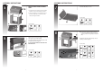
ASSEMBLY INSTRUCTIONS ASSEMBLY INSTRUCTIONS 1 Separate the 2 different types of wheels, 2 locking wheels (EH) and 2 regular wheels (EI). EI Attach the locking wheels (EH) to the back of the bottom shelf (EG) and the regular wheels (EI) to the front of the bottom shelf (EG). EH 3 Attach the front brace (CL) to the left and right cart side panels (EA and EB) CL TIP: One person should align the left side, while the second person assembles the right side.
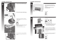
ASSEMBLY INSTRUCTIONS 5 ASSEMBLY INSTRUCTIONS THIS STEP REQUIRES 3 OR MORE PEOPLE. DO NOT ATTEMPT ALONE. EXTREMELY HEAVY. A + B 7 Attach the right side shelf fascia (DI) to the right side shelf table (DH), as shown. a. Position the top lid and burner box assembly (A and B) onto cart assembly (C) as shown. b. Use the hardware to connect both parts, on the left and right sides, at the three points indicated in Figure B and C.
ASSEMBLY INSTRUCTIONS ASSEMBLY INSTRUCTIONS 9 Front Attach the left shelf fascia (DB) to the left side shelf table (DA). 11 Remove the hardware that is pre-assembled to the side burner valve bracket (CC), as shown in figure A. Insert the side burner valve stem through the rear of the left side shelf fascia (DB). Assemble the side burner valve (CC) to the side shelf fascia (DB), using the hardware removed. CC Assemble the side burner control knob (#12) to the side burner valve (CC).
ASSEMBLY INSTRUCTIONS ASSEMBLY INSTRUCTIONS 12 a. Position the side burner (DD1) through the opening in the left side burner drip pan (DC). 13 Place the heat shield (CP) into the groove which is located at the back side of the front panel as shown in figure A. Next, attach the heat shield (CP) to the upper back panel (CO) by using the self tapping screws (x 4), as shown in figure B. THE HEAT SHIELD RESTS BELOW THE FRONT BRACE AND BACK PANEL. CP DD A DC A YOU WILL NEED: b.
ASSEMBLY INSTRUCTIONS ASSEMBLY INSTRUCTIONS 15 Place the flame tamers (BG) into the burner box. 17 a. Insert the grease tray (CM) into the opening in the upper back panel (CO), making sure to engage tracks located under burner box. b. Place the grease cup (CN) onto the tracks, located on the underside of the grease tray (CM). CO BG CM CN Model may not be exactly as shown. 16 a. Place the cooking grates (BH) into the burner box, as shown in figure A.
ASSEMBLY INSTRUCTIONS 19 FOR PROPANE MODEL ONLY. For natural gas model, follow step 20. a. Position the 20 lb propane tank onto the bottom shelf (EG), and secure using the bolt (already attached) located on the underside of the bottom shelf, as shown in figure B. A EG b. Attach the regulator coupling nut to the LP cylinder valve. F4 ATTENTION: For your families safety, do not attempt to light this BBQ until you have reviewed pages 4-7 of the CENTRO Safety & Care Manual.