D3, D5, A5 SLIDING GATE AUTOMATION Product Code: CP72SR5 INSTALLATION MANUAL Latest Revision: 02.02.2005 Document Ref.: 1010.D.01.
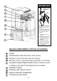
0 IMPORTANT 31 Oil Specifications: GRADE: 75W90 Qty: 75ml OIL LEVEL 32 33 34 35 WARNING! (D5/A5 ONLY) Fill with oil prior to running gearbox. For transport purposes this unit has been supplied with oil in a separate sealed container. 36 1. Lift off the cover to the operator. 2. Remove the control card and battery so that you can gain access to the filler plug. 3. Unscrew the cap and pour in the oil provided 37 38 NB. D3 is pre-filled with fluid grease.
TABLE 1 RUN (kgF) START (kgF) D3 25 GATE MASS (kg) 12 300 D5 60 20 500 D5 Light Industrial 16* 16* 500 A5 22 22 500 *LIMITED BY CAPACITY OF PSU 2
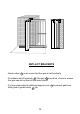
ANTI-LIFT BRACKETS - Guide rollers 39 must ensure that the gate is held vertically. - Fit suitable anti-lift brackets 42 . The gap 40 should be <5mm to ensure the gate cannot be lifted off the motor pinion. - For improved safety fit additional support post 41 to prevent gate from falling over if guide rollers 39 fail.
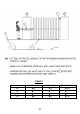
D5 A5 120 100 80 60 40 5 Pull ( kgf ) Time (hrs) A5 with FAN Duty Cycle ( % ) 120 100 80 60 40 20 30 25 20 15 0 5 0 Time (hrs) DUTY CYCLE CURVES - FOR THE WARRANTY TO BE VALID, ENSURE THAT THE DUTY CYCLE IS NOT EXCEEDED FOR THE PARTICULAR MOTOR BEING USED. * - DUTY CYCLE IS SUBJECT TO BATTERY AND CHARGER SIZE.
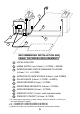
6 5 7 2 9 11 3 8 10 4 RECOMMENDED INSTALLATION AND CABLE THICKNESS REQUIREMENTS† 2 - LOCAL ISOLATOR 3 - MAINS SUPPLY (min 0.5mm² ‡, 2 CORE + EARTH) 4 - INTERCOM AND STATUS SIGNALING TO HOUSE (0.2mm², *n1 + 6 CORE) 5 - INTERCOM TO GATE STATION (0.2mm², #n2 CORES) 6 - PILLAR LIGHTS (0.5mm², 2 CORE + EARTH) 7 - RADIO RECEIVER (0.2mm², 3 CORE) 8 - PEDESTRIAN KEYSWITCH (0.2mm², 2 CORE) 9 - INFRA RED BEAM (0.2mm², 3 CORE) 10 - FREE EXIT LOOP (1.
MECHANICAL MOUNTING DETAILS Option 1 - Bolt down onto concrete plinth - Ensure motor does not protrude into drive-way install baseplate with centre line 250mm off pillar centre. - Position baseplate (43) with centre of single support stud (45) 105mm from edge of gate (46). (This dimension assumes centre line of rack (47) is 20mm from edge of gate). - Using the baseplate as a template mark and drill the 4 mounting holes into the concrete for the four M10 x 95 expansion studs.
M10 Nut M10 Washer Use two M12 plated nuts as spacers.
43 43 47 46 45 44 44 105mm 250m m 20mm CL CL 300mm 400mm 400mm MECHANICAL MOUNTING DETAILS Option 2 - Set into concrete plinth - Ensure motor does not protrude into drive-way install baseplate with centre line 250mm off pillar centre. - Fasten concrete anchors (44) to the baseplate (43) using the M10x45 bolts provided. Ensure that the bolts are well tightened. - Position baseplate (43) with centre of single support stud (45) 105mm from edge of gate (46).
350 mm 30 mm 46 47 43 PROVISION FOR CABLES - Ensure cables 46 are fitted through base plate 43 before concreting in place. - Remove knock-outs 47 from gearbox to allow for cable entry. - Route cables in front of battery (D3/D5 motors) as shown above. - Seal cable entry holes with silicone sealer.
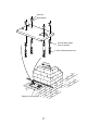
54 53 7 52 mm 54 51 GEARBOX MOUNTING DOWN DETAILS - Leave at least 7mm clearance between the lower gearbox nuts 52 and the baseplate to allow for later adjustment. - Gearbox MUST be firmly located between top & bottom nuts and washers 54 as shown at 51 . Use spring washer 53 to lock top nut in place. - Slide gearbox forwards or backwards to give ±8mm clearance between front of pinion and edge of gate.
55 ±300 mm 56 57 MOUNTING RACK - Attach steel rack to gate using 25x25x2mm angle brackets 55 . Distance between centerline of rack and edge of gate should be 20mm (see 56 ). - For best results support rack every 300mm. - Rack must be mounted level with a 2 - 3mm clearance 57 . USEFUL TIP l l l l 11 Raise gearbox by an additional 3mm. Put gearbox into manual mode (see........ 37 on page 22) Mesh rack and pinion fully and mount rack.
59 58 200 - 300mm LEVEL 200mm 60 MOUNTING RACK CONTINUED - A simple way of ensuring correct pitch spacing when joining steel rack is to clamp a small offcut 58 between the two pieces. - Check that weld 59 does not foul with meshing surfaces. - If RAZ ™ rack 60 is used, then start installing from the right hand side of the gate working towards the LHS. Use fastening screws e.g. “TEK” screws at least every 200mm.
65 IDLER PULLEYS 64 >100mm 61 >100mm 62 63 INSTALLING CHAIN DRIVE SYSTEMS - Weld rear anchor plate 61 onto gate such that centre line of tensioner pin 62 is in line with top of the shaft on the idler pulley 64 . Allow at least 100mm between idler pulleys and anchor brackets. - Align fixed anchor bracket 63 as for 61 . - Ensure chain direction over sprocket is as shown (see 65 ).
6mm 13mm <15kgF SETTING MECHANICAL CLUTCH (A5 ONLY) - Isolate MAINS POWER. - Remove fan from motor to expose the motor shaft (where applicable). Ensure fan has stopped turning. - Lock shaft using 13mm spanner and use 6mm allen key to adjust sensitivity - Clockwise to increase force. - Recommended maximum push force should not exceed 15kgF.
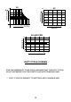
MOUNTING CONFIGURATION FOR STEEL RACK BOLT USING FASTENERS PROVIDED 66 WELD MOUNTING BRACKET PROVIDED TO STEEL RACK A HA RT TE A E GR ORIGIN MARKER BRACKET 0 N5 0m m 68 66 GREATER THAN 500mm B 66 66 C 13-20mm 68 MOUNTING OF GATE SENSOR - With the gate in the CLOSED position, mount the origin marker (66) a minimum 500mm from the origin sensor (68). (See isometric view (A) or plan view (B) above).Please note this distance will affect the pedestrian opening distance.
BLUE E COM LIGHT LIGHT BATT + BATT - MOTOR MOTOR COM LIGHT CP80 PSU1 LIGHT BATT - MOTOR MOTOR 12 N LIGHT COM GREEN/YELLOW L BROWN M1 M2 M3 BATT + CP80 CP81 17 15 M M 16 16 15 15 E E NL NL 75 13 L N E EN L L N E 21 13 76 18 14 20 - BATT BATT + 19 19 13 L N E 21 17 POWER WIRING (SEE PAGE 15 FOR SIGNAL WIRING) - 220V AC MOTOR WITH STARTING CAPACITOR 13 - 220V AC, 1Ø, MAINS SUPPLY FOR CP84E / CP83E USING REMOVABLE CONNECTORS 14 - CP83E POWER SUPPLY TRANSFORMER (
NEG 12V COM N/O NEG 12V NEG 12V 24 COM N/C SET LCK PED LED FRX IRB TRG +12V COM COM LIGHT LIGHT CP80 / CP81 22 23 25 26 27 28 29 SIGNAL WIRING (CP80 AND CP81) 22 - RADIO RECEIVER (OR OTHER TRIGGER e.g.
31 34 50 ENL 220V AC LNE INPUT 220V AC OUTPUT 49 TO CP80/CP81 PCB "DC IN” 43 48 RECOMMENDED LIGHTNING PROTECTION - For optimum lightning protection ensure earth cable from charger/PSU unit 34 is adequately earthed. - Use ring lug 49 to bond to baseplate mounting stud. - For additional protection bond baseplate 43 to earth spike 48 . - In event of damage to charger/PSU unit 34 disconnect quick release link 50 and push-on connector on controller.
1 2 3 4 5 END COMMISSIONING BLOCK DIAGRAM 1 - Check correct motor direction (pg. 20) 2 - Select programme mode (pg. 21) 3 - Setting of gate limits (pg. 22-27) NOTE: D3/D5 LIMITS ARE SET AUTOMATICALLY. A5 LIMITS ARE SET MANUALLY 4 - Function Selections(optional) (pg. 27-28) 5 - Timer/counter settings (optional) (pg. 29-30) Steps 1 to 3 must be done on initial commissioning. Steps 4 & 5 are optional.
CP80 CP81 12V DC 220V AC MOTOR a M1 M2 M3 b a TO 12V DC MOTOR c b TO 220V AC MOTOR SETTING MOTOR DIRECTION CP80 GATE CLOSES: - a TOWARDS LEFT (ABOVE) BLACK TOWARDS RIGHT BLUE CP81 b a b c BLUE BLUE BLACK RED BLACK RED BLACK BLUE ENSURE THAT MOTOR WIRE COLOURS ARE AS PER TABLE ABOVE 20
1 CP80/CP81 2 L1 13.8V L2 CP80/CP81 L1 3 L2 CP80/CP81 L1 L2 STATUS STATUS STATUS SET SET BLACK 72 SET RED 69 71 70 SELECTING PROGRAMME MODE STEP 1 - Remove power from control card: - for A5 remove electronics power only 69 - for D3/D5 remove battery power 70 as well as electronics power 69 . STEP 2 - Fit “SET” link 71 . STEP 3 - Reapply power (reversal of STEP 1). STATUS LED will flash 5 times on power up. Check that LED L2 and “SET” are ON.
Fig.1 1/2 1/2 73 37 Fig.2 SETTING GATE LIMITS - Rotate manual release thumbwheel 37 fully clockwise, or until clutch is fully dis-engaged and gate can be moved by hand. D3/D5 ONLY - Slide gate approximately half way open. See 73 above (FIG. 1). - Re-engage gearbox. A5 ONLY - Slide gate to fully closed position (FIG. 2). - Leave gearbox dis-engaged. - Skip to page 25-27 and follow START MANUAL GATE LIMITS ROUTINE.
CP80/CP81 control card L1 L2 TEST STATUS SET SETTING GATE LIMITS (continued) NB. Ensure you follow the correct procedure! The procedure for setting D3/D5 and A5 motors is DIFFERENT. The A5 limits have to be set manually (see page 25 and 26), while the D3/D5 motors set their limits automatically (see page 21 to 23). D3/D5 ONLY (PAGE 23, 24, 25) - Press the TEST pushbutton while monitoring LED L1. - When L1 flashes once, release TEST pushbutton. L2 will go out, L1 will continue to flash once per second.
D3/D5 MOTOR AUTOMATIC SET-UP 1 1- Gate starts at “crawl” speed to open gate. NB. If gate closes, remove power and reverse motor wires (see page 20) 2 2- Gate hits “open” end stop and reverses direction running at crawl speed. 3 3 - Gate hits “closed” end stop and reverses direction running at “FULL” speed until the marker, then at CRAWL speed to end. 4 4 - Gate hits “open” end stop and reverses but now runs at “FULL” speed. 5 6 5 - As gate sensor passes the motor, the speed reduces to CRAWL.
TURBO MODE: If desired the set up time can be shortened by manually overriding the automatic “crawl”speed in steps 1, 2, 3 shown on page 24. This is done by pressing and holding the TEST button. The speed increases to FULL speed while the button is depressed. NB. Do not run the gate into the end stops at full speed.
A5 MOTOR MANUAL SET-UP STEP 1 ALIGN ORIGIN SWITCH - Start with gate fully closed. - Push gate open (origin marker must have moved well past origin switch). - Push gate closed again. STEP 2 - ENSURE PCB IS IN PROGRAMME MODE (refer procedure page 21) STEP 3 - SET LIMITS - Press TEST pushbutton until LED L1 flashes once and release. - L1 will continue to flash once and L2 will go out.
CP81 control card CP81 control card L1 L2 TEST STATUS 74 L1 L2 TEST STATUS SET SET EXIT GATE LIMITS ROUTINE (A5 ONLY) If the gate limits described on page 26 are successfully completed, then LED L2 will be ON. - Position SET link as shown above 74 to exit programming unless proceeding to other menus. FUNCTIONS SELECT Several different functions can be programmed.
TABLE 2 MAIN MENU SUB DIVISION OF MAIN MENU No of times L1 flashes AUTO CLOSE No of times STATUS must flash 2 4 MODE COLLISION SENSITIVITY 7 POSITIVE CLOSE MODE 9 PREFLASHING* 10 1 ON 2 OFF 1 STANDARD 2 CONDOMINIUM 3 PIRAC 4 REVERSING 1 HIGH 2 MEDIUM 3 LOW 1 ON 2 OFF 1 MODE1 2 MODE 2 3 MODE 3 4 OFF FACTORY DEFAULTS HIGHLIGHTED 28
*The PREFLASHING MODES mentioned on page 28 are described below: MODE 1 - COURTESY LIGHT PREFLASHES AT 1 HZ, THEN ACTS AS COURTESY LIGHT. MODE 2 - COURTESY LIGHT FLASHES AT 1 HZ FOR PREFLASH TIME AND THEN FLASHES IN SYNCHRONISM WITH THE STATUS LED WHILE THE MOTOR RUNS. MODE 3 - COURTESY LIGHT ON CONTINUOUSLY FOR PREFLASH TIME AND MOTOR RUN TIME ONLY. TIMER and COUNTER SETTING Various timers and counters can be programmed. The procedure is described below in conjunction with Table 3, page 30.
TABLE 3 MAIN MENU UNIT OF MEASURE Each flash No of times of STATUS L1 flashes represents FACTORY DEFAULTS NORMAL AUTOCLOSE 3 1 SEC 15 SEC PEDESTRIAN AUTOCLOSE 5 1 SEC 5 SEC COURTESY LIGHT 6 10 SEC 12x10 SEC AUTOCLOSE OVERRIDE 8 1 SEC 3 SEC PREFLASH TIME 11 1 SEC 5 SEC COLLISION COUNTER 12 1 COUNT 4 COUNTS CRAWL DISTANCE (D3/D5) 13 350 MM † 1x350mm COAST MODE (A5) 13 10 MM 30mm † THE CRAWL DISTANCE IS A LENGTH OF TRAVEL WHICH ALLOWS THE GATE TO SLOW DOWN BEFORE REACHING THE
PROCEDURE TO PROGRAMME CONTROLLER BACK TO FACTORY SETTINGS 1. REMOVE POWER (POWER SUPPLY AND BATTERY IF D3 or D5). 2. FIT THE "SET" LINK. 3. CONNECT "PED" AND "FRX" TO "COM". 4. RECONNECT POWER. L1 AND L2 WILL ILLUMINATE. 5. REMOVE THE POWER (BATTERY AND POWER SUPPLY). 6. REMOVE THE "SET" LINK AND DISCONNECT "PED" AND "FRX" FROM "COM". 7. THE CARD IS NOW PROGRAMMED TO DEFAULT SETTINGS AS SHOWN IN TABLES 2 (see page 28) AND TABLE 3 (see page 30) (GATE END POINTS ARE NOT AFFECTED).
2. GATE DOES NOT RUN BUT THE RELAYS ENERGISE WHEN THE UNIT IS ACTIVATED. 2.1 Faulty motor circuit 2.1.1 Faulty motor relay / FET 2.1.2 Motor fuse blown (replace with 16/20A slow blow 5x20mm) 2.1.3 Fuseholder making bad contact. 2.1.4 Worn motor brushes 2.1.5 Loose motor wire 2.1.6 Faulty controller 3. GATE OPENS ON ITS OWN. 3.1 Permanent trigger input 3.1.1 Check for latched Rx or latched house pushbutton 3.2 Intermittent fault on pushbutton line (underground joint with moisture build-up) 3.
CENTURION THE AUTOMATIC CHOICE CENTURION SYSTEMS (PTY) LTD HEAD OFFICE: TEL: +27 (0)11 699-2400, FAX: +27 (0)11 704-3412 or 462-6669 148 EPSOM AVENUE, NORTH RIDING P.O. BOX 506, CRAMERVIEW, 2060 SOUTH AFRICA WEB: http://www.centsys.co.za General information e-mail: info@centsys.co.za FOR TECHNICAL SUPPORT CONTACT: SOUTH AFRICA EAST RAND. . . . . . . . . . . . . . . (011) 397-6401 DURBAN . . . . . . . . . . . . . . . . . (031) 701-9583 NELSPRUIT . . . . . . . . . . . . . . . (013) 752-8074/5 PRETORIA . .