
Installation manual

page 13
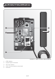
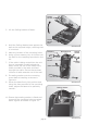
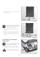
11. Run the cable through the Calling Module
base and then hook the Calling Module
into the base as shown in Figure 13 and
clip back into position.
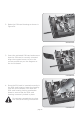
12. Terminate cable onto the voice
communication terminal. Refer to wiring
diagram in Figure 30 for details.
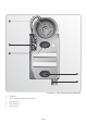
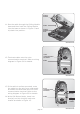
13. If the cable is surface-mounted, route
the cable into the unit from underneath
as shown and terminate onto the voice
communication terminal. Refer to the
wiring diagram in Figure 33 for details.
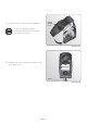
14. Write Call Button labels, insert into
lens(es) and clip lens(es) back onto
chassis as shown in Figure 15.
FIGURE 13.
FIGURE 14.
FIGURE 15.
Cable
Calling
Module
Calling
Module
base
Voice
communication
terminals
Cable
Cable
Voice
communication
terminals
Lens
Labels