VECTOR2 installation manual LINEAR SWING GATE OPERATORS
Company Profile Company Profile 1986 In-house R&D development team 100% testing to specifications 1990 1995 1999 CENTSYS today Manufacture to international quality standard ISO 9001:2008 Competent after-sales technical support Sales and technical support to over 50 countries worldwide CENTURION SYSTEMS (Pty) Ltd reserves the right to make changes to the products described in this manual without notice and without obligation of CENTURION SYSTEMS (Pty) Ltd to notify any persons of any such revision
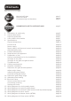
Contents Mechanical Setup Electrical Setup Commissioning and handover page 1 Page 2 page 2 IMPORTANT SAFETY INSTRUCTIONS page 3 page 5 Declaration of conformity General description page 6 Lightning protection page 7 page 7 3. Icons used in this booklet page 8 4. Specifications Physical dimensions PAGE 8 Control card page 10 Power supply page 10 Power supply, wall box and control card assembly page 10 Allowable gate mass page 10 page 12 5. Product identification page 14 6.
19. 20. 21. 22. 23. 24. 25. Charger and Pillar Light connections Setting up additional features Menu navigation map Controller features Factory defaults schedule Description of terminal functions Diagnostics Diagnostic LEDs Gate status LEDs LCD display Buzzer feedback 26.
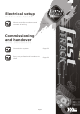
Mechanical setup These quick steps are for the experienced installer who needs a checklist to get a standard installation up and running in the minimum of time. Detailed installation features and functions are referred to later in this manual.
Electrical setup Mount controller enclosure and connect all wiring Page 33 Commissioning and handover Commission system Page 64 Carry out professional handover to client Page 64 Page 2
IMPORTANT Safety Instructions ATTENTION To ensure the safety of people, it is important that you read all the following instructions. Incorrect installation or incorrect use of the product could cause serious harm to people. The installer, being either professional or DIY, is the last person on the site who can ensure that the operator is safely installed, and that the whole system can be operated safely.
! ! ! ! ! ! ! ! ! ! ! ! ! ! Make sure that an earth leakage circuit breaker with a threshold of 30mA is fitted upstream of the system Never short circuit the battery and do not try to recharge the batteries with power supply units other than that supplied with the product, or by CENTSYS Make sure that the earthing system is correctly constructed, and that all metal parts of the system are suitably earthed Safety devices must be fitted to the installation to guard against mechanical movement ri
1.
2. General description The VECTOR2 operator has been designed to safely and cost-effectively automate a wide variety of swing gates, from single light-domestic swing gates to heavy industrial double swing gates. The fail-safe and fully redundant position and Collision Detection system has been designed and tested to set the standard in safety of operation and to provide an unparalleled level of reliability and durability in operation.
Lightning protection The VECTOR2 electronic controller utilises the same proven surge protection philosophy that is used in all CENTSYS products. While this does not guarantee that the unit will not be damaged in the event of a lightning strike or power surge, it greatly reduces the likelihood of such damage occurring. The earth return for the surge protection is provided via the mains power supply earth.
4. Specifications Physical dimensions Model V400 1400mm Extended 1000mm Retracted 400mm Stroke m 0m 95mm 10 All dimensions shown in millimeters FIGURE 1. OVERALL DIMENSIONS Model V500 1600mm Extended 1100mm Retracted 500mm Stroke m 0m 95mm 10 All dimensions shown in millimeters FIGURE 2.
Technical specifications VECTOR2 400 Input voltage Motor voltage Motor power supply Battery charger Domestic Light-industrial Current consumption (mains) Current consumption (motor at rated load) Operator push force - maximum Operator stroke Piston extension / retraction speed Typical gate opening time Manual override Maximum number of operations per day Duty cycle - mains present Operations in standby with 7Ah battery Half day Full day Collision sensing Controller solenoid output rating Operating temperatu
Control card Maximum motor current per channel 15A (fused) Maximum input voltage 18V DC Standby current draw 48mA Maximum solenoid current draw 2A DC Maximum aux output current 3A (PTC) Collision detection Current sense and redundant optical Position and trajectory Redundant optical Temperature range -20°C to +60°C Power supply 7Ah, 12V, CP84E (Domestic) Nominal input voltage 77Ah, 12V, CP84SM2A (Light -industrial) 220-240V AC ±10% @ 50Hz 220-240V AC ±10% @ 50Hz AC current draw (maximum)
Allowable gate mass Maximum allowable gate mass for V400 operator: Gate swing angle Up to 1.5m Up to 2m Up to 2.5m Upto 3m(#1) Up to Up to 3.5m(#1) 4m(#1) 90° 500kg 500kg 500kg 360kg 260kg 200kg 100° 500kg 500kg 388kg 160kg 190kg 150kg 130kg 110° 500kg 306kg 198kg 120° 180kg 100kg 65kg (#1 - an electric lock must be fitted to secure gate in closed position) Maximum allowable gate mass for V500 operator: Gate swing angle Up to 1.5m Up to 2m Up to 2.5m Upto 3m(#1) Up to 3.
5. Product identification 12 1 2 13 14 3 15 4 5 16 6 17 7 8 18 15 7.5 19 20 21 9 22 10 23 11 FIGURE 3A. PRODUCT IDENTIFICATION 1. 2. 3. 4. 5. 6. 7. 8. 9. 10. 11. 12. Wall bracket (standard) Wall bracket pin VECTOR2 gate operator (complete assembly) 12mm snap ring Gate warning decal VECTOR2 control card version 2 built in receiver Charger 12V 7.
9 1 2 10 3 11 4 5 1 12 13 14 6 15 7 16 8 FIGURE 3. PRODUCT IDENTIFICATION 1. 2. 3. 4. 5. 6. 7. 8. Padlock Wall bracket (high security) VECTOR2 securing plate (short) Guard retainer Piston guard M6x16 Countersunk cap screw Gate bracket spreader plate M6 Hexnuts 9. 10. 11. 12. 13. 14. 15. 16.
6. Required tools and equipment ! Spanner - 17mm, 15mm, preferably socket set ! Crimping tool and pin lugs ! Hammer ! Electric drilling machine ! 20mm hole saw ! Screwdrivers - 6mm Philips, 3.5 Flat ! Pliers ! Connector block ! 2 x G-clamps ! Masonry Bits - 12mm; 10mm for wall mount brackets; steel bits 6.5mm/10.
7. Preparation of site General considerations for the installation ! Always recommend the fitment of additional safety equipment such as safety edges and safety beams, for additional protection against entrapment or other mechanical risks ! Check that no pipes or electrical cables are in the way of the intended installation ! Check that enough space is available for the gate operator with the gate in the required open position.
Strength of the pillar For reliable operation it is important to ensure that the way the operator is secured to the wall takes into account the strength of the pillar, the size of the gate, and how frequently the gate would be used: High Security Kit together with a Wall Adaptor Kit Pillar This mounting is highly recommended for all light industrial gates, or for heavy gates of any length. Alternatively it should be considered for use on pillars of low or unknown strength.
As important as the bracket is how the bracket is secured to the pillar Pillar Through wall Applications: ! Prefabricated walling ! For heavy gates operating frequently Best FIGURE 8 Pillar Chemical anchors Applications: ! Masonry pillars ! Frequent use Works well FIGURE 9 Pillar Welding Applications: ! Lighter gates ! Domestic Works well FIGURE 10 Pillar Sleeve anchors Applications: ! Lighter gates ! Domestic ok FIGURE 11 RAWL Bolts Pillar Applications: ! Very light ! Very domestic Not re
Strength of the gate and gate bracket The gate adaptor kit both strengthens the connection to the gate, and also allows for more flexibility when mounting the bracket to the gate: Welding Gate adaptor kit Applications: ! Light-industrial ! Heavy gates ! Frequent use Best FIGURE 13 Through bolts Gate adaptor kit Applications: ! Light-industrial ! Heavy gates ! Frequent use Very good FIGURE 14 Welding Applications: ! Domestic ! Medium gates ! Frequent use Good FIGURE 15 Through bolts (High tensile
The Mechano kit This kit is useful when fitting VECTORS to existing installations, and also makes adjustments easier when doing new installations. FIGURE 17. MECHANO KIT INSTALLATION OPTIONS FIGURE 18.
8. Cabling requirements Control box 9 8 Mains isolator switch 7 3 11 9 4 6 1 To dwelling Be 5 ni nc a 2 10 5 FIGURE 19. CABLING REQUIREMENTS Legend 1a. 220-240V AC mains cable via mains isolator 1b. Low-voltage 16V AC battery charger supply switch (3 core LNE 0,5mm²), or (2 core 1,5mm²). 2. Intercom cable (n1 + 6 core) to house. 3. Master motor (MTR M) or Slave motor (MTR S) cable ( minimum, 2 core 2mm2 + 4 core 0,5mm² multi-stranded) see note 4.
9. Operator installation To simplify the installation process, it is recommended that the existing gate is removed from the pillar before proceeding. Closed 1. Determine gate opening angle and direction of operator (inward or outward). 120° 60° 110° 100°90° 80° 70° Ope n Alternatively the swing angle can be determined more accurately with the process detailed on page 31 Estimate swing angle FIGURE 20. ESTIMATE SWING ANGLE 2.
4. Secure the bracket to the wall with the most appropriate means. It is critical that the wall bracket is securely mounted. See page 14 for site considerations. FIGURE 24 Determine the gate bracket position Start with the operator fully retracted. Turn out the actuator tube one or two turns. 5. Fit the gate bracket to the operator. One or two turns FIGURE 25 6. Fit the motor end of the operator to the wall bracket. FIGURE 26 7. Open the gate fully and temporarily clamp the gate bracket to the gate.
8. Unlock the operator and swing the gate closed. 9. Remove the pin and the operator from the bracket, check that there are at least one or two turns of the actuator before it is fully extended. FIGURE 28 If it becomes obvious that the operator does not have enough stroke, reduce either the A or B distances by moving the wall Be sure not to make the A and B values less than allowed for in the installation tables on page 26 and 27.
12. Fit operator, gate bracket pins and snap rings As an alternative to the snap ring, fit a padlock. or FIGURE 31 Adjust origin clamp 14. Slide the origin clamp along the actuator tube, right up to the operator. Secure in place with an allen key tighten properly. Open 13.Unlock the operator and open the gate fully FIGURE 32 1 15. Attach warning decals to the gate as shown.
Inward swing gate Setup Gate open Ga te op en Gate closed FIGURE 34 A B For gates opening 90° or less: FIGURE 35 For best security (but slower operation) install with large B value For fast operation (but less security) install with small A and small B values A B For gates opening more than 90°: Ensure that the gate does not exceed the gate mass specifications on page 10.
For V400 (400mm operator) 1400mm Extended 1000mm Retracted FIGURE 37 0° Recommended positions (Only for a 2.5m gate or shorter) Gate opening angle Gate swing angle A Value B Value 90° or less 150 150 100° 155 155 110° 125 125 120° 110 110 120° 60° 110° 100° 90° 80° 70° FIGURE 38 Alternative positions Gate swing angle A+B should not A and B must each be greater exceed Up Up to Up to Up to Up to to1.5m 2m 2.5m 3m 3.
For V500 (500mm operator) 1600mm Extended 1100mm Retracted FIGURE 39 0° Recommended positions (Only for a 2.5m gate or shorter) Gate opening angle Gate swing angle A Value B Value 90° or less 150 150 100° 155 155 110° 125 125 120° 110 110 120° 60° 110° 100° 90° 80° 70° FIGURE 40 Alternative positions Gate swing angle A+B should not A and B must each be greater exceed Up Up to Up to Up to Up to to1.5m 2m 2.5m 3m 3.
For gates opening 90° or less: B make up bracket to suit A FIGURE 41 For best security (but slower operation) install with large B value For fast operation (but less security) install with small A and small B values For gates opening more than 90°: B make up bracket to suit Ensure that the gate does not exceed the gate mass specifications on page 8. A FIGURE 42 Endstop see Caution Note Outward opening swing gates must have physical endstops fitted in the open position.
For V400 (400mm operator) 1400mm Extended 1000mm Retracted FIGURE 44 0° Recommended positions (Only for a 2.5m gate or shorter) Gate opening angle Gate swing angle A Value B Value 90° or less 150 150 100° 155 155 110° 125 125 120° 110 110 120° 60° 110° 100° 90° 80° 70° FIGURE 45 Alternative positions Gate swing angle A+B should not A and B must each be greater exceed Up Up to Up to Up to Up to to1.5m 2m 2.5m 3m 3.
For V500 (500mm operator) 1600mm Extended 1100mm Retracted FIGURE 46 0° Recommended positions (Only for a 2.5m gate or shorter) Gate opening angle Gate swing angle A Value B Value 90° or less 150 150 100° 155 155 110° 125 125 120° 110 110 120° 60° 110° 100° 90° 80° 70° FIGURE 47 Alternative positions Gate swing angle A+B should not A and B must each be greater exceed Up Up to Up to Up to Up to to1.5m 1.5m 2.5m 3m 3.5m Up to 3.
10. Determine gate swing angle Use this procedure to accurately determine the gate opening angle: Step 1 1. Close the gate and measure a distance of 1m from the centre-line of the gate hinge. 2. Make a mark on the ground. 1m FIGURE 48 Step 2 3. Open the gate and measure a distance along the gate a distance of 1m from the centreline of the gate hinge. 4. Make a mark on the ground. 5. Measure the distance on the ground between the two marks (Z). 1m 6.
11. Allowable wind load Wind speeds for which operator will still operate the gate (for V400 or V500 operators) For a 25% covered gate: (Palisades, etc.) x 1.8m high Value of A or B dimension once installed. #1 Up to 1.5m Up to 2m Gate lengths: Up to Up to 2.5m 3m(#2) Up to 3.
12. Electrical Setup 1. Always check that the circuit breaker in the electrical panel is in the OFF position, and that all high voltage circuits (more than 42.4V) are completely isolated from the mains supply before doing any work. 2. Ensure that all low voltage systems (less than 42.4V) are suitably protected from damage, by disconnecting all sources of power such as chargers and batteries before doing any work. 3.
Com FRX LIT LED Com Aux 12V Com Saf Sol 4. Check that the charger and battery are connected to the controller. Ensure the battery polarity is correct. Light Light 5. Switch on the mains supply (via isolator). Batt + Batt MTR M+ MTR M MTR S+ MTR S - 6. Ensure that both the controller and charger are effectively earthed for improved lightning protection. FIGURE 52 Setting the limits open 7. Check that the origin has been correctly set. (See page 24). FIGURE 53 8.
13. Wiring diagram for closing safety beam Closing safety beam 12V/24V - IRB Receiver 12V/24V + COM NC NO IRB Tx 12V/24V + 12V/24V - FIGURE 56.
14. Wiring diagram for opening safety beam Opening safety beam 12V/24V - IRB Receiver 12V/24V + COM NC NO IRB Tx 12V/24V + 12V/24V - FIGURE 57.
15. Wiring diagram for external radio receiver and loop detector Loop Loop and loop detector Loop detector 12V + NEG COM NC NO External radio receiver 12V + NEG COM NC NO Remote control circuitry Refer to diagram only if external receiver is being used and not the onboard receiver, disable onboard receiver - Menu 11 FIGURE 58.
16. Wiring diagram for other inputs Solenoid or strike lock Holiday Lockout keyswitch/keypad (normally-closed) Pedestrian keyswitch/keypad (normally-open) Pillar Light pushbutton (normally-open) CENTURION A U X Status LED FIGURE 59.
17. Wiring diagram for Master motor (MTRM) Thin purple Master motor (MTR M) Thin blue / orange Thin red / grey Thin black S Sens1 S Sens2 M Sens1 M Sens2 Sens+ SensSafe CLS Safe OPN Com LCK/STP TRG PED Com FRX LIT LED Com Aux 12V Safe Com Sol Light Light Thick blue Thick black Batt + Batt MTR M+ MTR M MTR S+ MTR S - FIGURE 60.
18. Wiring diagram for Slave motor (MTRS) Thin purple Thin blue / orange Slave motor (MTR S) Thin red / grey Thin black S Sens1 S Sens2 M Sens1 M Sens2 Sens+ SensSafe CLS Safe OPN Com LCK/STP TRG PED Com FRX LIT LED Com Aux 12V Safe Com Sol Light Light Thick blue Thick black Batt + Batt MTR M+ MTR M MTR S+ MTR S - FIGURE 61.
19. Charger and Pillar Light connections S Sens1 S Sens2 M Sens1 M Sens2 Sens+ Sens- Auxiliary supply 220 E -240V AC N Mains in L L N E E L Protection fuse on mains input to charger (rating: 250mA slow blow) Pillar Light Neutral Safe CLS Safe OPN Com LCK/STP TRG PED Com FRX LIT LED Com Aux 12V Safe Com Sol Light Light Live Batt + Batt MTR M+ MTR M MTR S+ MTR S - FIGURE 5.
20. Setting up additional features Figure 62 provides the full menu of features that can be set up on the system. Explanation of each feature is provided in the section ‘Controller features’. When setting up the VECTOR2 system via the LCD display, all the steps that have to be followed are clearly provided via the display. It is only necessary to note the following: 1. To get into setup mode, press the (oblong) button for three seconds and follow the instructions provided from there. 2.
21. Menu navigation map 1. Setting limits 2. Safety 2.1. MTRM Collision Force 2.2. MTRS Collision Force 1.1. Setup wizard 2.1.1. MTRM Opening Collision Force 2.1.2. MTRM Closing Collision Force 2.2.1. MTRS Opening Collision Force 2.2.2. MTRS Closing Collision Force 2.3. Collision Count 3. 3.1. 3.2. 3.3. 3.4. Autoclose Autoclose status Autoclose timer Autoclose override Autoclose advanced options 4. Modes of Operation 4.1. Operating Mode 5. Run profile 5.1. Positive Close 3.4.1.
2.3 5.2 Leaf delay 5.2. 5.3. 5.4 5.5. 5.6. 5.7. 5.8. 5.9. 5.10. 5.11. Pre-open delay Pre-close delay Opening speed Closing speed Ramp-up distance Ramp-down distance TRG stop distance IRB stop distance Crawl distance Torque limit 6. 6.1. Infrared beams PIRAC control 6.2. IR beam test 6.3. IRBO=IRBC on closing IR beam alarms 6.4. 2.1.1. Leaf Delay Status 2.2.1. Leaf Delay Value 6.1.1. PIRAC status 6.1.2. Stop on open 6.1.2.1. Stop on open status 6.1.2.2. Stopping distance 6.2.1. Status 6.2.2.
8. 8.1. 8.2. Courtesy light Courtesy light timer Light profile 9. 9.1. 9.2. General settings Operating standard Reset options 9.3. Diagnostic screen status Test button disabled status Backup eeprom Restore eeprom 9.4. 9.5. 9.6. 8.2.1. 8.2.2. 8.2.3. 8.2.4. 9.2.1. 9.2.2. 9.2.3. 9.2.4 9.2.4.
22. Controller features Menu 2 - Safety (collision force) ! Collision force If the gate is obstructed, the internal collision circuitry will activate. The response of the system to a collision will vary, depending on the profile (operating standard, e.g. ZA,) selected. Responses can vary from the gate stopping, to the gate reversing. The collision force can be set from minimum to maximum in five discrete steps. A sixth step will disable collision sensing entirely, allowing maximum force to be achieved.
! Autoclose on partly closed - automatically close the gate if it is stopped while closing, but before reaching the fully closed position More than one advanced option can be selected Menu 4 - Modes of Operation It is possible to select the following Modes of Operation: Standard, Condominium, Reversing, PLC and Deadman Control Mode (DMC). All modes are triggered by closing a normally-open contact between the Trg input terminal and the Com terminal.
! Short Stop value The Short Stop distance can be set between 1mm and 40mm of piston stroke. ! PCM push force The amount of force applied by the actuator when in PCM can be set as a value from 1 to 15 ! Leaf delay Leaf delay is used in cases where one gate leaf must move before the other. The most common need for this arises when a mechanical 'lip' is fitted to one of the gates.
! Ramp-up distance Sets the ramp-up distance in millimeters of travel of the piston when starting. This setting applies to both motors ! Ramp-down distance Sets the ramp-down distance in millimeters of travel of the piston when stopping. This setting applies to both motors. ! Crawl distance Sets the final crawl distance in millimeters of travel of the piston when reaching an endpoint. This setting applies to both motors. ! Push force limit Sets the maximum push force delivered by the motors.
Additional beam functionality is provided: ! PIRAC Outside closing beam The Passive-Infrared Autoclose feature allows the gate to close automatically, as soon as a vehicle or pedestrian has passed through the closing beam. This security feature ensures that the gate stays open for the minimum amount of time possible.
! IRBO=IRBC Configures the opening beam to act as a closing beam while the gates are closing. This allows one set of beams to be used across the line of the driveway up to where the gates open. ! IR beam alarms While the gate is fully closed, this feature allows the following alarms: ! Ambush alarm Activates an alarm if either the opening or closing beams have been continuously interrupted for a predefined time.
Menu 7 - Pedestrian Opening This feature is associated with the Ped input on the controller. When activating this input, the system will open the gate to the pedestrian open position, and then automatically close after the Pedestrian Autoclose time lapses.
! Pre-release time Sets the time period (in 0.1s increments) for which the lock releases BEFORE the gate has started moving. This is useful in cases where premature gate movement prevents the lock from releasing ! Lock location Specifies whether the gate is locked while closed, open of both ! Lock drive Specifies if the lock is to be powered by an AC or DC voltage.
! Mode C will turn on the courtesy light during the pre-opening and pre! closing delays, as well as while the gate is moving In these pre-flashing modes, the timed courtesy light functionality is not available Menu 10 - General features ! ! Operating standard Regional operating standards can be set. Applying this setting will automatically configure the controller settings to conform to the specific regions standard (e.g.
! ! Another benefit of using the shift button system is that it requires both hands to operate the two button combination. This prevents the user from accidentally enabling sensitive functions such as holiday lockout on the controller Each transmitter learned into the system is assigned a unique transmitter ID.
South African standard profile - ZA Parameter Description Unit Minimum Default Maximum PED Open Distance % (Full Open) 10 30 100 PED Autoclose Time S 0 5 240 PED Pre-Open Delay Time S 0 2 240 PED Pre-Close Delay Time S 0 0 240 Gate Lock Enabled Gate Lock Type Gate Lock Pre-Release Time Gate Lock Release Time Gate Lock Location Yes/No No M,S Striker S 0.1 S 0.1 0.0 24.0 24.0 1.0 24.
23.
24. Description of terminal functions S Sens1 Motor S (MTR S) operator. Connects to the thin PURPLE wire of the Motor S operator. S Sens2 Motor S (MTR S) operator. Connects to the thin BLUE or ORANGE wire of the Motor S operator. M Sens1 Motor M (MTR M) operator. Connects to the thin PURPLE wire of the Motor M operator. M Sens2 Motor M (MTR M) operator. Connects to the thin BLUE or ORANGE wire of the Motor M operator. Sens + Operator sensor power connection.
TRG Trigger input. (A normally-open potential-free input) Momentarily connecting this input to COM will cause the gate to open or close depending on the operating mode selected. For more information see the Autoclose feature and Modes of Operation PED Pedestrian opening input. (A normally-open potential-free input). Momentarily connecting this input to COM will cause one gate to open to the Pedestrian open position. For more information refer to the Pedestrian feature FRX Free-exit input.
Light Pillar Light connection. These two terminals provide a normally-open potential free contact which is generally used to switch on a pillar light (courtesy light). This contact is fuse protected – refer to page 41 for fuse specifications. Batt + Positive battery connection. (Battery terminal normally indicated as + or RED) Batt - Negative battery connection. (Battery terminal normally indicated as - or BLACK) MTR M+ Motor M operator power connection. (Thick BLUE wire).
25. Diagnostics Diagnostic LEDs The controller is fitted with diagnostic lights (LEDs) that assist with the set-up and maintenance of the gate.
LCD display The LCD display shows useful information regarding the status of the system. S Sens1 S Sens2 M Sens1 M Sens2 Sens+ Sens- 2 1 4 3 A OFF L 5 0:00 CLOSED 6 Safe CLS Safe OPN Com LCK/STP TRG PED Com FIGURE 72. CONTROLLER SCREEN 1. Battery icon Indicates the state of charge of the battery. ! Four solid bars = full capacity ! Two solid bars = 50% capacity ! No solid bars, with the icon flashing = battery empty 2.
Buzzer feedback A warning buzzer will sound (where applicable) as per the table below: Priority Number of beeps Fault type Gate continues to operate User can correct error Break-in alarm 1 Continuous tone for 30 seconds Alarm N/A N/A Ambush alarm 2 Continuous tone until IRBs are cleared Alarm N/A N/A Battery low 4 3 beeps periodically for 30 seconds Power system fault Yes* Yes Multiple collision 3 Periodic until condition is cleared by user (500/500ms) Collision No Yes Auxiliary
26. Installation handover Once the installation has been successfully completed and tested, it is important for the installer to explain the operation and safety requirements of the system. NEVER ASSUME THE USER KNOWS HOW TO SAFELY OPERATE AN AUTOMATED GATE! Even if the user has used one before, it does not mean he knows how to SAFELY operate it. Make sure that the user fully understands the following safety requirements before finally handing over the site.
Notes
0.07.B.0026 VECTOR2 10July2012 Installation manual -5Jul2012 www.centsys.com.