
Instruction manual


16
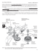
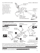
Assemble the tail rotor input
shaft by sliding two Ball Bearings
on to the shaft followed by the
large Bevel Gear (B). Align the holes
on the gear with the hole in the
shaft and press in one M2x12
pin and secure with one
M3x4 Set Screw (Tip 1)
using threadlock.
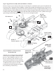
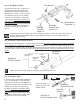
Notice that the tail rotor output drive
shaft has 2 holes, one through the
shaft and one drilled partially into the
shaft. Slide the small bevel gear (A)
with the teeth facing the shaft from
the end with the through hole and
position the gear aligning the holes.
Press the M2x12 steel pin through
and secure with one M3x4 Set
Screw (Tip 1) inserted from the end
of the shaft using threadlock. Slide
the Spacer Tube onto the shaft and
position against the gear.
2x12mm Pin
#HW3073
Tail Rotor Drive
Shaft
#HI3075
Small Bevel
Gear A
M3x4 Set
Screw
(small hex key)
#HW3074
Spacer Tube
Hole through
shaft
Step 24 Tail Output Shaft Assembly
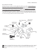
#HI3089
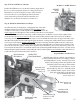
Tail Pitch Ball
Links x 2
M2x8 Pin x 2
The tail pitch plate and tail
pitch ball links are pre-
assembled. (Note: apply
some JB weld to the outside
of the lock ring to avoid the
assembly loosening.) Apply
a drop of CA glue between
the edge of the brass tube
and the plastic pitch plate.
Put this assembly aside for
now.
#HI3087A
Tail Pitch Plate
Pre-Assembled
#CNBB1350
5x13 Ball
Bearing x 2
#HW3070
Tail Gearbox Input
Shaft
2x12mm Pin
M3x4 Set
Screw
(small hex key)
#HI3075
Large Bevel Gear B
Step 25 Tail Pitch Plate Assembly
Step 26 Tail Input Shaft Assembly
#CNBB1060
6x10 Ball
Bearing x 2