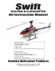
Swift ELECTRIC R/C HELICOPTER Kit Instruction Manual Mechanical Specs: Main Rotor Blades: 520-550mm Tail Rotor Diameter: 21cm Length: 105cm Height: 34.4cm Weight: 1.54kg (configured with brushless motor and servos) Electronic Specs: Speed Control: 50-80 Amp Motor: 900-1250kv (based on battery) Battery: 4S-6S Li-Po or 12 cell NiMH or NiCd Pinion: 9-15 tooth Head Speed: 1600-2100 RPM Century Helicopter Products Designed and Developed in USA 1st Edition August 2006 All rights reserved.
1. Introduction Congratulations on your purchase of Century Helicopter Product’s Swift 16 Kit. The Swift 16 has taken the electric market by storm in providing a high performance machine at the perfect size for stable outdoor flight. The attention is well deserved as the Swift is unmatched in affordability, quality and performance. In order to take advantage of the Swift’s performance capabilities we recommend using a high quality computer radio system with 120 degree and/or 140 degree eCCPM mixing.
2. Battery Warnings & Safety Lithium Polymer Battery Safety For Lithium Polymer and NiMH/NiCD cell or battery packs purchased. 1. 2. 3. 4. 5. 6. 7. 8. 9. 10. 11. 12. 13. 14. 15. 16. Never fast-charge any battery type unattended. Never charge Li-Poly cells or battery packs at any rate unattended. Only charge Li-Poly cells or battery packs with a charger designed specifically for lithium polymer chemistry.
3. Required Items for Operation This is the general list of items required to get the Swift helicopter flying. Century produces a full spectrum of accessories and tools to assemble your helicopter. The Swift is a mechanical cyclic collective pitch mixing type helicopter requiring a standard helicopter radio (the helicopter radio does not require eCCPM type mixing for this model). The Swift uses 4 servos to operate critical systems. Gyroscopes are required to operate the model safely.
4. Before You Begin Every attempt has been made to ease the assembly of your kit, at each step where there are complex instructions there are detailed written instructions to walk you through each step. Remember to take a few minutes before each step to carefully examine each step to become familiar with the parts and assembly before beginning that step.
. Assembly Instructions Main Blade Grip Cap Screw M4x30 (CNM4x30) A C Cap Screw M3x16 (CNM4x16) *Raised lip should be facing the bearing Bearing M3x6x2.5 (CNBB364) Brass Spacer M3x5x3 (CNE524) Spacer M3x5x2 (CNE524) Bell Mixing Arm (CNE524) Linkage Ball (CNLR104) Add a small amount of Synthetic Hydro Carbon Grease Bearing M3x6x2.
6.
6. Assembly Instructions Adjusting the Flybar Equal flybar length on each side Flybar outer flat spot D LO C K Flybar control arms must be level with Seesaw. Set screws face upward. TH R EA Flybar outer flat spots align with flybar control arms when arms are flush with seesaw. Swashplate and Washout Assembly C Flat Washer M3x5x.5 (CNLR1003) A Washout Base (CNE516) Main Shaft (CNE508) Linkage Ball (CNLR1014) Washout Control Arm (CNE516) Bearing 3x6x2.
6.
6.
6. Assembly Instructions Tail Transmission Assembly M4x30 Pin (CNE533) M3x10 Cap Screw (CNM3x10CS) C A Upper Transmission Case (CNE542) M3x4 Set Screw Brass Spacer M4x6x.25 (CNLR1006) Do not over tighten Transmission Gear (CNE533) Bearing 4x10x4 (CNBB4102) Tailboom (CNE532) Tail Belt Drive (CN531) Brass Spacer M4x6x.
6.
6. Assembly Instructions Landing Gear Assembly Cap Screw M3x18 (CNM3x18CS) Cap Screw M3x25 (CNM3x25CS) (L/R) Main Frames (CNE503) Set Screw M3x4 (CNM3x4SS) Landing Gear Spacers (CNE512) C A Hint: Place strut into a cup of warm water, if skid does not slide through the hole of the strut. *Apply CA to M3x4 set screw. Landing Struts (CNE512) C A Hint: Landing Gear Spacers (CNE512) are a pressure fit molded material it fits in one direction only. Verify the contour shape of the spacers.
7. Putting Together Your Model Assembling the Components After completing the previous steps, the following instructions are for putting together the sub-assemblies. Please follow the instructions and any hints along the way to ensure that you have a properly flying model. M3x12 Self tapping screws (8) Do not fully tighten the screws till the following step. 1) Align the mounting posts from the front transmission gearbox with the mounting posts at the rear of the main frame.
7. Putting Together Your Model Servo Linkage Lengths 1) Before proceeding to measure and install the pushrods, make sure you have adjusted the flybar to it’s optimal level. Adjust the flybar until the outer flat spots align with the set screws in the flybar control arms (set screws facing upward and flybar control arms are flush up against the seesaw).
8. Installing and Adjusting Control Components Adjusting the Servos There are three servos that are mounted on the left and right main frames. They work together to tilt the swashplate producing the collective pitch, roll cyclic pitch (aileron control) and the fore-aft cyclic pitch (elevator control). Before beginning this section you should center all servos using the radio. All servo arms must be set with linkages as pictured at 90 degree angles. All servos mount with M2.
8. Installing and Adjusting Control Components CCPM Servo Guidelines The goal in the end after all the servos are mounted is to have the swashplate sit level or at 90 degrees to the main shaft and have the swashplate move equally fore, aft and side to side. The swashplate will also travel up and down as the three servos work together.
8. Installing and Adjusting Control Components Setting Tail Rudder Pushrod & Blades 1) When setting up the pitch of the tail blades, the tail pitch plate should be first set in the middle position of the tail rotor shaft. The tail blades should have no pitch in that position. Tighten the tail rotor blades until the blade grips hold firm yet soft enough so that the tail blades can still fold back in the event of a blade strike.
9. Final Preparations Mounting the Gyro (Optional Item) CNE555 Carbon Gyro Mounting Plate can be used to mount the gyro at the rear of the helicopter. It is extremely important that the gyro is attached using only the supplied two sided tape onto a clean flat surface. Keep all wires and components away from the gyro housing. Do not use straps or elastics to secure the gyro.
9. Final Preparations Preparing, Mounting & Tracking The Main Rotor Blades (1) Each rotor blade has 3 holes drilled in the root. Use epoxy to glue the plastic root ends to the exposed wood pre-cut by the factory. Use the countersunk screws to secure the root ends to the blades and let the glue dry. (2) Use the 2 M4x30 blade bolts and M4 locknuts to secure the blades to the blade grips on the main rotor head. Main rotor blades should have their leading edge turning clockwise.
10. Setup and Adjustment Final Adjustments - Radio Setup Now that the servo installation into the helicopter is finished the following pages should be reviewed. As various types of radios can be used to setup the helicopter, some of the following information may not apply. Servo Direction (Servo Reversing) Check that all servos move in the correct directions.
11. Final Preparations Final Adjustments - Tail Rotor Setup Once the tail rudder pushrod is adjusted correctly so the tail does not rotate ( don’t consider wind now ) the revolution mixing can be adjusted. *Revolution Mixing The revolution mixing function allows the helicopter to climb or descend without the tail rotating. These setting are set when using regular piezo rate gyros, if using a Heading Hold gyro remove all tail mixing. There is a high & low setting on the helicopter radio.
12. Pre-Flight Basic Hovering When all is set, ready and checked, attach your training gear/pod and plug in your battery. 1) 2) 3) 4) Place the helicopter pointing into the wind and stand behind the model about 15’ away. Always watch the nose of the helicopter, move the rudder left and the nose will move left. Start by increasing the throttle slowly until the helicopter rises 2-6 inches off the ground then set it back down.
13. Replacement Parts 24.
13. Replacement Parts CNE534 Rudder Control Rod Set CNE535 Fin Mounts CNE536 Carbon Fiber Fin Set CNE537 Tail Pitch Slider CNE538 Tail Pitch Lever CNE539 Tail Rotor Hub CNE540 Tail Blade Grips CNE541 Tail Rotor Blades CNE542 Tail Transmission Gear Box CNE543 Tail Boom Support Set CNE544 Tail Servo Mounts CNE545 Pushrod Set CNE547 Elevator Servo Spacers (2) CNE548 520mm Main Blades CNE552 M3x5x3.