Swift Carbon 620SE ELECTRIC R/C HELICOPTER Kit Instruction Manual Mechanical Specs: Main Rotor Blades: 600-620mm Tail Rotor Blades: 75-85mm Length: 113.3cm Height: 34.4cm Weight: 1.76kg (configured with brushless motor and servos) Electronic Specs: Speed Control: 50-85 Amp Motor: 800-1250kv (based on battery) Battery: 4S-10S Li-Po Main Gear: 96 Tooth Pinion: 9-14 Tooth Head Speed: 1600-2300 RPM Century Helicopter Products Designed and Developed in USA 2nd Edition May 2008 All rights reserved.
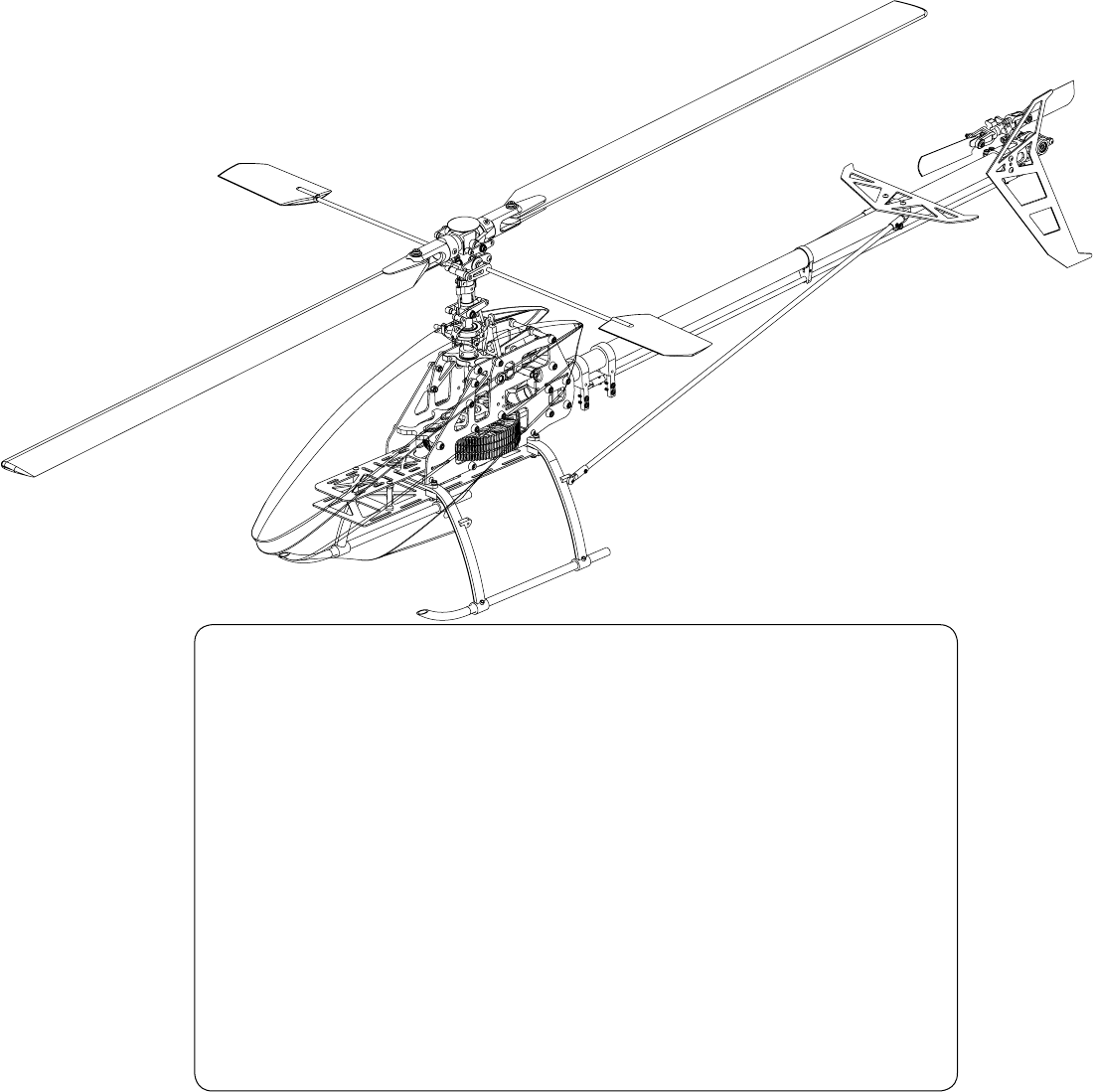
1. Introduction Congratulations on your purchase of Century Helicopter Product’s Swift Carbon 620SE Kit. The Swift Carbon 620SE is a high performance machine providing the agilitiy and durability that is expected out of a helicopter of this caliber. The attention and praise by the R/C helicopter community is well deserved as the Century Swift line is unmatched in affordability, quality and performance.
2. Battery Warnings & Safety Lithium Polymer Battery Safety For Lithium Polymer and NiMH/NiCD cell or battery packs purchased. 1. 2. 3. 4. Never fast-charge any battery type unattended. Never charge Li-Poly cells or battery packs at any rate unattended. Only charge Li-Poly cells or battery packs with a charger designed specifically for lithium polymer chemistry.
3. Required Items for Operation This is the general list of items required to get the Swift Carbon 620 helicopter flying. Century produces a full spectrum of accessories and tools to assemble your helicopter. The Swift Carbon 620 is a electronic cyclic collective pitch mixing type helicopter requiring a standard helicopter radio (the helicopter radio requires eCCPM mixing for this model). The Swift Carbon 620 uses 4 servos to operate critical systems. Gyroscopes are required to operate the model safely.
4. Before You Begin Every attempt has been made to ease the assembly of your kit, at each step where there are complex instructions there are detailed written instructions to walk you through each step. Remember to take a few minutes before each step to carefully examine each process to become familiar with the parts and assembly before beginning that step. All hardware associated with the part has been bagged and bundled together.
. Assembly Instructions LO Cap Screw M4x30 (CNM4x30) TH R EA D B C K Main Blade Grip Cap Screw M3X16 (CNM3x16) Attaches to feathering shaft on the following page *Raised lip should be facing the bearing Bearing 3X6x2.
6.
6. Assembly Instructions Adjusting the Flybar Flybar outer flat spot Equal flybar length on each side Flybar outer flat spots align with flybar control arms when arms are flush with seesaw. TH R EA D LO C K Flybar control arms must be level with Seesaw. Set screws face upward. C LO D R EA C A Flat Washer M3X5x.5 (CNLR1003) R Washout Base (CNE516) TH Head Block K Swashplate and Washout Assembly Linkage Ball (CNLR1014) CNC Washout Control Arm (CNE560) Bearing 3X6x2.
6.
6. Assembly Instructions LO C TH R EA D B Upper Bearing Block (CNE593) K Main Frame Assembly Included in the kit are silver screw caps which act as washers for the M3 screws on the main frame assembly. You can choose to use these if you wish during the main frame assembly.
6. Assembly Instructions Tail Gear Box Assembly *The thrust bearing washer with the bigger inner race should be closer to the head block. The thrust bearing washer with the smaller inner race should be closer to the rotor blade. The proper way to install the thrust bearing is with the loose balls (open end) of the thrust bearing facing inwards toward the center of the rotorhead. This is so that as the blades spin, the grease does not spin outwards off the bearing carrier due to centrifugal force.
6. Assembly Instructions Autorotation Hub Assembly Auto-rotation Hub and Bearing (CNE510B) Optional Stacked Gear Setup (For High Voltage Power Systems) This triple stacked gear system is required for power systems that are using 10S (37 volts) Swift HD Main Gear (CNE510ABK) Bevel Head Cap Screw (CNM3X8FHCS) M3 Lock Nut Main Gear Hub Spacer (CNE592A) This is an optional item that distributes the torque across the main gears more evenly. You will also need a longer motor pinion to use this system.
6. Assembly Instructions Tail Transmission Assembly M4x30 Pin (CNE533) M3X10 Cap Screw (CNM3X10CS) C A Upper Transmission Case (CNE542) M3X4 Set Screw Brass Spacer M4x6x.25 (CNLR1006) Do not over tighten Transmission Gear (CNE533) Bearing 4x10x4 (CNBB4102) Tailboom (CNE532A) Tail Belt Drive (CN531A) Brass Spacer M4x6x.25 (CNLR1006) C A Lower Transmission Case (CNE542) M4x4 Set Screw Do not over tighten Note: Straighten the belt inside the tailboom, rotate the belt 90-degree counter clocwise.
6.
6.
7. Putting Together Your Model Assembling the Components After completing the previous steps, the following instructions are for putting together the sub-assemblies. Please follow the instructions and any hints along the way to ensure that you have a properly flying model. M3X12 M3 Cap Screws (8) Do not fully tighten the screws till the following step. Look at gear mesh through here. 1) Align the mounting posts from the front transmission gearbox with the mounting posts at the rear of the main frame.
7. Putting Together Your Model Servo Linkage Lengths 1) Before proceeding to measure and install the pushrods, make sure you have adjusted the flybar to it’s optimal level (flybar paddles flat and parallel to the ground). Adjust the flybar until the outer flat spots align with the set screws in the flybar control arms (set screws facing upward and flybar control arms are flush up against the seesaw).
8. Installing and Adjusting Control Components Adjusting the Servos There are three servos that are mounted on the left and right main frames. They work together to tilt the swashplate producing the collective pitch, roll cyclic pitch (aileron control) and the fore-aft cyclic pitch (elevator control). Before beginning this section you should center all servos using the radio. All servo arms must be set with linkages as pictured at 90 degree angles. All servos mount with M2.
8. Installing and Adjusting Control Components CCPM Servo Guidelines The goal in the end after all the servos are mounted is to have the swashplate sit level or at 90 degrees to the main shaft and have the swashplate move equally fore, aft and side to side. The swashplate will also travel up and down as the three servos work together.
8. Installing and Adjusting Control Components Setting Tail Rudder Pushrod & Blades 1) When setting up the pitch of the tail blades, the tail pitch plate should be first set in the middle position of the tail rotor shaft. The tail blades should have no pitch in that position. Tighten the tail rotor blades until the blade grips hold firm yet soft enough so that the tail blades can still fold back in the event of a blade strike.
9. Final Preparations Mounting the Gyro The built in Gyro Mounting Plate can be used to mount the gyro at the rear of the helicopter. It is extremely important that the gyro is attached using only the supplied two sided tape onto a clean flat surface. Keep all wires and components away from the gyro housing. Do not use straps or elastics to secure the gyro.
9. Final Preparations Preparing, Mounting & Tracking The Main Rotor Blades (1) The Swift Carbon 620 does not come with main rotor blades. Please refer to the instructions included with your blades (must be purchased separetely and are not included with the Swift Carbon 620 kit). (2) Use the 2 M4x30 blade bolts and M4 locknuts to secure the blades to the blade grips on the main rotor head. Main rotor blades should have their leading edge turning clockwise.
10. Setup and Adjustment Final Adjustments - Radio Setup Now that the servo installation into the helicopter is finished the following pages should be reviewed. As various types of radios can be used to setup the helicopter, some of the following information may not apply. Servo Direction (Servo Reversing) Check that all servos move in the correct directions.
11. Final Preparations Final Adjustments - Tail Rotor Setup What separates airplane radio equipment from the helicopter version is in the control of the individual curves discussed earlier and in the Revo-mixing*. Take a moment to consider the helicopter hovering in front of you. 1 Nose rotates left at hover 2 Nose rotates right at hover Problem: Not enough pitch in tail rotor to match torque setting of motor. Problem: Too much pitch in tail rotor to match torque setting of motor.
12. Pre-Flight Basic Hovering When all is set, ready and checked, attach your training gear/pod and plug in your battery. 1) 2) 3) 4) Place the helicopter pointing into the wind and stand behind the model about 15’ away. Always watch the nose of the helicopter, move the rudder left and the nose will move left. Start by increasing the throttle slowly until the helicopter rises 2-6 inches off the ground then set it back down.
13.
13.
14.
15. Upgrades/Accessories/Tools CNE610HE High Efficiency Main Gear (Gray) CNE610AS Triple Gear Gear Upgrade Kit CN2017 Kryptonite Hex Drivers M5, M3, M2.5, M2, M1.5 CN2282S Metal Tail Pitch Slider CNMG509L Motor Gear- 9T, 5MM,1.0, Long CN2027 G-Force Pitch Gauge CNE274 Century Outrunner 600A+ 1100kV CN2051 Accuratech Blade Balancer v.2 CNE594 Aluminum Washout Hub CN2236 CNC Triple B.B Tail Assembly CNE275 Century Outrunner 650A+ 800kV CN2050 Paddle Gauge v.
Notes
Notes