P/N.
FCC COMPLIANCE STATEMENT FOR AMERICAN USERS This equipment has been tested and found to comply with the limits for a CLASS A digital device, pursuant to Part 15 of the FCC Rules. These limits are designed to provide reasonable protection against harmful interference when the equipment is operated in a commercial environment.
WARRANTY INFORMATION .......................................................................................... II CHAPTER 1 – BARCODE PRINTER .............................................................................. 1 1-1 Introduction.......................................................................................................................... 1 1-2 Printer Models .....................................................................................................................
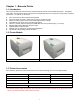
Chapter 1 - Barcode Printer 1-1. Introduction The Century Systems FALCON 4D series is a desktop thermal transfer / direct thermal label printer. With plastic outer casing, the FALCON 4D series is designed to be a lightweight and a low cost printer for large variety of printing requirement.
1-4. General Specifications Model Name Resolution Print Mode CPU Sensor Location Sensor Type Sensor Detection Print Speed Print Length Print Width Media Ribbon Printer Language Software Resident Fonts Fonts Download Image Handling Barcode Interface Interface Transmission Memory LED Display Power Environment Humidity Cert.
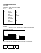
1-5. Communication Interface Parallel Interface Interface cable Pin out : Parallel cable compatible with IBM PC : See below PIN NO.
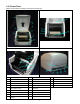
1-6. Printer Parts Please use the following diagrams to identify each printer part. 1 Cover Open Button 11 LED Light (Ready) 21 Power Socket 2 Top Cover 12 LED Light (Status) 22 USB Port 3 Label Roll Core 13 FEED Key 23 Parallel Port 4 Ribbon Rewind Wheel 14 Print Line Adj.
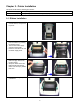
Chapter 2 - Printer Installation This printer model has the following print modes: Thermal Transfer (TT): When printing, ribbon must be installed to transfer the print contents onto the media. Direct Thermal (DT): When printing, no ribbon is necessary; it only requires direct thermal media. 2-1. Ribbon Installation 1. Place the printer onto a smooth surface, and open the top cover. 2. Loosen and then lift the upper print mechanism by pressing the locking tenons. 3.
2-2. Label Installation 1. Open the top cover. 2. Place the label roll onto the Label Roll Core, 3. Loosen and lift the upper print mechanism by pressing the locking tenons. 4. Feed the label through the two Label Guides to the Tear-off Bar. Align the label guides to the label edge. 5. 6. Close the upper print mechanism from the top to finish label installation.
2-3 Label Roll Core Installation Instruction (A) 1” roll core installation instruction (B) 1.
2-4 Card / Hang tags Installation When installing cord tags, the tag hole must align with the sensor arrow (as indicated in Photo 1), then use the Label Guide to secure the tags. Tag hole position Sensor Detection Position (Photo 1) 2-5. USB Installation 1. USB is a Plug & Play facility. Once the USB cable is connected from PC to the printer, PC will automatically detect the new device and begin the installation process.
2. Select ” Search for a suitable driver for my device [recommended]“ and click “Next” 3. Select the location of the driver. 4.
5. The USB device is built on the serial port, therefore make sure the interface setting is specified to the assigned port. 6. Go to Control Panel\System\Device Manager and the USB port will be listed under Ports (COM & LPT). The example from the right hand side indicates that the USB Serial Port is COM3. 7. After the USB driver is installed, the USB device can be used through software (such as QLabel III or Century Systems drivers) to print labels. 2-6.
2-7. PC Connection 1. Please make sure the printer is powered off. 2. Take the power cable, plug the cable switch to the power socket, and then connect the other end of the cable to the printer power socket. 3. Connect the cable to the parallel port on the printer and on the PC. 4. Power on the printer. The LED light (Ready) should turn green when power is on. NOTE: If you wish to connect with an USB interface, please install the USB driver first.
Chapter 3 - Options Installation 3-1. Stripper Parts 27 28 Stripper Module Screw (TAP 3*8) x 2pcs [NOTE]: Please power off the printer before installing the stripper module. 3-2. Stripper Installation 1. Open the top cover by pressing the Cover Open Buttons on both sides. 2. Push the front cover piece buttons inward to open. Lift/take off the front cover piece according to the direction shown in the photo. 3. 4.
6. Place the right side in first, and then fit the left side. 7. Hold the stripper module and tighten the screws (28). 8. Peel off the first label, and feed the liner through the roller and the peel off bracket. Flip close the stripper module. 9. 10. Close the print mechanism, then press the FEED key.
3-3.
3-4. Cutter Parts 29 Cutter Module 30 Screw (TAP 3*8) x 2pcs [NOTE]: Please power off the printer before installing the cutter module. [NOTE]: Do not cut self-adhesive labels! The traces of adhesive will pollute the rotary knife and impair safe operation! 3-5. Cutter Installation 1. Open the top cover by pressing the Cover Open Buttons on both sides. 2. Push the front cover piece buttons inward to open. Lift/take off the front cover piece according to the direction shown in the photo. 3.
4. Open the mechanism by pressing the Locking Tenon, plug in the cable connector of the cutter module (29) onto the switchboard socket. Note: There are 2 sockets on the converting boards (one is for stripper installation, another is for cutter installation), before plug the connector into socket, please check the pin first. 5. Clip in the right side of the cutter module (29) first, then secure the left side. 6. Flip the cutter module (29) down to open the cutter. Note: Please refer to photo (A).
7. Hold the cutter module and lock it with the two side screws (30). 8. After the screws are locked, flip close the cutter module. 9. Close the mechanism to complete the cutter module installation. 3-6. Extended Memory Parts 31 32 Extended Memory Card PCB Pillar x 2pcs [NOTE]: Please power off the printer before installing the extended memory.
3-7. Extended Memory Installation 1. Open the top cover by pressing the Cover Open Buttons on both sides. 2. Take off the media roll spindle. Open and remove the plastic cover on the inner base. 3. Secure the PCB pillar onto the main board. 4. Check the pins where the memory is to be connected to, then plug the memory card onto the main board.
3-8. Ethernet Parts 33 34 35 36 37 Ethernet Module Connector Cable Network Board Stand Screws (MACHINE 3x6) x 2 Screw (TAP 3x8) x 1 Please turn power off when assembling Ethernet module. 3-9. Ethernet Installation 1. Remove screws at the bottom of the printer (refer to arrows). 2. Facing the printer, exert force on two sides of the printer and remove the middle compartment. 3.
4. Secure Ethernet Module (33) and Network Board Stand (35) together as shown in Figure 2 。 (Figure 2) 5. Screw the secured module and stand onto the bottom of the printer. 6. Connect one end of the Connector Cable (34) to the printer main board and the other end to Ethernet Module. Note: Bend the cable inward when making the connection to prevent interference with the main board. 7. To complete installation, put the middle compartment back and rescrew it onto the bottom of the printer.
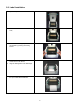
Chapter 4 - LED Message Description 4-1. LED Status FEED LED Ling READY Green STATUS READY Green (Flash) STATUS Orange READY Red (Flash) STATUS Orange Beep Status 1 Normal status 3 Dump Mode, 3 Self-Test READY Orange (Flash) 3 STATUS Orange READY Red (Flash) 3 STATUS Red READY Orange (Flash) 3 STATUS Red READY STATUS Description Normal status Printers currently in Dump Mode, for operation instructions please refer to 4-4. Printing Self-Test page, for operation instructions please refer to 4-3.
Model & Version Serial Port Setup CFD-4206: V1.200 Serial port: 96,N, 8,1 Test Pattern Number of DRAM installed Image buffer size Number of forms Number of graphics Number of fonts Number of Asian fonts Free memory size Speed, Density, Ref.
4-4. Dump Mode When label setting and the print result don’t match, it’s recommended to go into the Dump Mode to check whether there’s a mistake in data transmission between the printer and the PC. For example, when printer receives 8 commands, yet without processing these commands, only print out the contents of the commands, this will confirm whether the commands were received correctly. Test procedures to enter the Dump Mode are as follows: 1. Power off the printer, press and hold the Feed key. 2.
4-7. Error Messages LED Message Print head is opened Entering the Cooling Process Out of ribbon or check ribbon sensor Out of media or check media gap sensor LED Light Beep Ready Status 4 beeps Red twice Description Print head not firmly in place. Red None Print head temperature high. Red 3 beeps twice Ribbon not installed, and printer shows error message. Ribbon used up or ribbon supply shaft not moving.
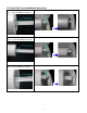
Chapter 5 - Maintenance and Adjustment 5-1. Thermal Print Head Cleaning Unclear printouts (some parts unable to print) may be caused by dusty print head, ribbon stain, or label liner glue, therefore when printing, it’s necessary to keep the top cover closed. Also, check and prevent paper/label from being stained or dusty to ensure print quality and to prolong the print head life. Print head cleaning instructions are as follows: 1. 2. 3. 4. 5. Power-off the printer. Open top cover. Take out the ribbon.
5-3. Print Line Adjustment Use print head adjusting gear to adjust the contacting surface between print head and label. To get better printing balance and quality. 1, When turning print head adjusting gear counterclockwise (as arrow 1 shows), print head would move in a direction where arrow A is. 2. When turning print head adjusting gear clockwise (as arrow 2 shows), print head would move in a direction where arrow B is. 5-4. Adjust the cutter 1.
5-5.