C E N T U RY S E R I E S LM O WNER ' S M ANUAL
Congratulations on your purchase of a Century Series console. All of us at Crest Audio in Paramus, New Jersey, USA, support your decision, knowing your console contains the finest combination of design and manufacture in the industry. While your new Century Series console is one of the most feature-packed available, great effort has been put into making it simple to operate. This manual explains the functions of your new console, how they operate and how they relate to each other.
TABLE OF CONTENTS LM Feature Overview 2 LM System Connections 3 A brief description of the LM design, features and functions. Contains diagrams illustrating conventional system connections. LM Wiring Conventions 5 Contains diagrams indicating how connectors for Crest consoles are wired. LM Power Supply 6 A description of the rack-mountable Century Series consoles power supply. LM Power Connections 7 A description of Crest console power connections.
LM CENTURY SERIES Feature Overview The Century Series was designed to have all the features and functions demanded by the modern music professional. The engineers at Crest Audio have delivered the finest combination of function and sonic accuracy in an affordable intuitive console. The features listed below are common to all Century Series LM Consoles. • SSM/PMI High quality devices on balanced microphone/line inputs and on all outputs for uncompromised audio quality and reliability.
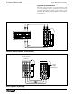
CENTURY SERIES LM LIVE MONITOR CONSOLE System Connections The console is the nerve center of a sound system and controls most of the variables within a system. Proper connection and component relationships are vital to assure accurate operation and results. The following diagrams illustrate conventional system connections.
CENTURY SERIES LM 6001 Professional Power Amplifier Clip/Limit Signal Temp/DC Active -6 -10 -6 -3 -10 -15 -3 -15 -1 -30 -80 -1 -30 0dB -80 Ch A 0dB Ch B 6001 Professional Power Amplifier Clip/Limit Signal Temp/DC Active -6 -10 -3 -6 -10 -15 -3 -15 -1 -30 -80 0dB Ch A -1 -30 -80 0dB Ch B Floor Wedge Connection Receivers for In-Ear Monitors Transmitters for In-Ear Monitors Stereo In-Ear Monitor Connection PAGE 4
CENTURY SERIES LM Wiring Conventions Since the same connectors are used throughout the professional audio industry, it is important to know how the connectors for Crest’s Century Series are wired. The wiring is as follows.
CENTURY SERIES LM Power Supply Century Series Consoles use a separate rack-mountable power supply which provides the specific voltages used by each console. Century Consoles make use of two different power supplies. The model and frame size of your particular console determines which of the two supplies should be used.
CENTURY SERIES LM Power Connections The connections to and from the power supply vary depending on your specific configuration. Multiple power supplies can be daisy-chained to provide fail-safe protection in the event of a supply failure. When two or more supplies are used, they may be connected to the same mains voltage since only one of the supplies will actually be feeding the console at any given time.
CENTURY SERIES LM 3 7 2 9 4 5 4 6 3 7 2 8 1 9 10 0 PAD GAIN 20 The LM-12 input module is the primary input control for the LM12 monitor console. It differs from the LM-20 input module only in the mix send section. 10 0 +48V LINE LM-12 INPUT MODULE 8 1 48V Phantom Power Switch PRE Turns on 48V Phantom Power as required by certain microphones for proper operation. 30 10 4 5 5 6 3 6 60 7 2 8 100 0 4 ø 10 5 7 2 8 9 1 HF 0 10 3 4 5 1.
CENTURY SERIES PFL Switch Samples the channel’s signal pre-fader and allows for monitoring within the master section of the console. This signal is not affected by the Mute Switch. When depressed, the signal level can be seen on the output 12 meter, and heard via the mixer’s headphone or local monitor output. When this PFL Switch is depressed, the channel PEAK LED indicator illuminates at a lower intensity.
CENTURY SERIES LM 3 7 2 9 4 5 4 6 3 7 2 8 1 9 0 PAD 10 GAIN 20 This module serves as the input module for LM-20 and the nowdiscontinued LM-8+4. The only difference between the two is the factory default settings on the dual concentric sends.For the LM-20 the sends are set for level/level operation. For an LM8+4 the sends are set for level/pan operation.
CENTURY SERIES MUTE Switch with LED Mutes the channel and all sends. This switch does not affect the PFL switch or the Peak and Signal Present LED indicators, The LED illuminates when the channel is muted either from the local mute switch or the scene mute system. PFL Switch Samples the channel’s signal pre-fader and allows for monitoring within the master section of the console. This signal is not affected by the Mute Switch.
CENTURY SERIES LM 4 20 OUTPUT 2 40 +9 RETURN +6 +3 4 5 6 3 0 7 2 -3 1 9 0 -6 4 -9 1 5 6 3 -12 2 7 2 8 1 -15 1 8 9 0 1 -18 5 SUB INPUT 4 5 6 1 3 7 1 3 1 1 2 20 HF O + 8 1 9 0 8 8 4 3 1 1 5 6 1 7 2 1 8 1 1 3 9 0 60 1 5 8 30 MID O + 8 ø 8 1 1 15 30 10 INSERT ON 6 1 4 LF TB ENB O + 8 8 BAL OUT 1 1 DIM EQ IN MUTE INSERT SEND HPF 8 10 PFL 4 20 PEAK 2 40 RETURN 4 1 5 6 3 7 2 1 8 1 INSERT RTN SIG 5 9 0 4 1 5 6 3 0
CENTURY SERIES LM LM-12 Output Module The LM-Mono Group output module is the primary output module on the LM-12 and the secondary output module on the LM-8+4 and the LM-20 Output PEAK & Signal LEDs Output Meter The green LED constantly displays the level of signal activity by varying in intensity. Monitors the post-fader output signal via a ten-segment LED array. Output EQ Controls the the equalization of the output mix signal through three bands, via six controls.
CENTURY SERIES LM 100 40 200 OUTPUT 400 20 +9 RETURN +6 +3 4 9 0 4 -9 8 1 9 0 -18 3 15 20K 2 HF 8 8 1 8 9 0 10 4 5 6 12 7 3 16 1K 10 SUB INPUT 4 5 6 11 3 7 10 O + 2 8 1 3 9 0 600 2 7 2 -15 16 10 5 6 3 -12 1 8 1 -6 1K 7 2 -3 5 5 6 3 0 10 5 MONO 8K 300 MID O + 8 Ø 8 16 16 150 300 100 INSERT ON 6 1K 40 LF O + 8 TB ENB 8 BAL OUT LEFT 16 16 DIM EQ IN MUTE INSERT SEND HPF 80 100 PFL 40 200 INSERT RETURN PEAK 20 400 SIG RETUR
CENTURY SERIES LM LM-8+4 Output Module The LM-Stereo group output module is the primary output module on the discontinued LM-8+4. Output Meters Monitors the post-fader output signal via two ten-segment LED arrays. Output EQ Controls the the equalization of the output mix signal through three bands, via six controls. The upper knob of each band determines the center frequency (high-1kHz-20kHz, mid300Hz-8kHz, low-40Hz, 1kHz), while the lower knob adjusts the amount of boost or cut.
CENTURY SERIES LM 40 200 20 OUTPUT 400 +9 RETURN +6 5 6 4 +3 3 0 7 2 1 -3 -6 -9 9 0 10 4 5 6 3 8 1 -15 2 7 2 -12 1 8 9 0 10 -18 5 SUB INPUT 4 5 6 11 3 7 10 3 15 1K 2 20K HF O + 8 8 16 9 0 10 4 5 6 12 7 3 2 16 1K 8 1 8 1 9 0 3 600 5 10 A B 8K 300 MID O + 8 Ø 8 INSERT ON 16 16 150 300 100 6 TB ENB 1K 40 LF O + DIM 8 8 16 BAL OUT LEFT 16 PEAK EQ IN SIG INSERT SEND MUTE HPF 80 100 INSERT RETURN 40 200 PFL 20 400 RETURN 4 5
CENTURY SERIES LM LM-20 Output Module The LM-Dual group output module is the primary output module on the LM-20. Output Meter Output PEAK & Signal LEDs The red LED indicates that the output is within 3dB of the clipping point. Monitors the post-fader output signal via two ten-segment LED arrays. The green LED constantly displays the level of signal activity by varying in intensity. Output EQ Output Faders Controls the the equalization of the output mix signal through three bands, via six controls.
CENTURY SERIES LM OUTPUT BAL OUT INSERT SEND INSERT RTN MONITOR A LEFT MONITOR A RIGHT EXT TB IN PAGE 18
CENTURY SERIES LM LM Master Module A Output 11 Talkback Enable This the first of two modules that include master controls for all LM consoles in addition to mono output eleven. Injects the talkback signal from the master section into the group output. Output Meter Output 11 Dim Switch Monitors the post-fader output signal of group 11 via a tensegment LED array. Introduces a -6dB drop to the output signal. This is a push on/push off switch, not momentary.
CENTURY SERIES LM OUTPUT BAL OUT INSERT SEND INSERT RTN MONITOR B LEFT MONITOR B RIGHT OSC IN PAGE 20
CENTURY SERIES LM LM Master Module B This the second of two modules that include master controls for all LM consoles in addition to mono output twelve. Output Meter Monitors the post-fader output signal of group 12 via a tensegment LED array. This meter also indicates PFL level. PFL Indicator This LED illuminates when the signal on meter 12 is a PFL or AFL signal Talkback Mic Input Allows for connection of a gooseneck or other XLR type microphone to the talkback system.
LM Appendix A Technical Information
CENTURY SERIES LM Specifications The following are the technical specifications for the Century LM console. Frequency Response +0.0, -0.5dB, 20Hz to 20 kHz (referenced to 1kHz) Total Harmonic Distortion Mic input to Group output 20Hz to 20 kHz at +15dBu <0.
CENTURY SERIES LM LM Block Diagram PIN 1 LIFT BAL MIC IN BAL MIC OUT BAL LINE IN INSERT SEND INSERT RETURN PAD P DIRECT OUT ROTARY POT +48V XFORMER OPTION P LED 15dB PAD P AMP MIC PRE 1KHZ OSC GAIN 20 30 40 +48v LINE S GAIN 6 - 60DB HPF SIGNAL PRESENT INPUT PREAMP BAL DRIVER TO PEAK SWITCH OSC Ø USER OPTION INSERT SEND INSERT RETURN GROUP 12 OUT MONITOR A RIGHT MONITOR A LEFT EXT TB OUT EXT TB IN M M FADER LF PFL SW H MID HF SHELF EQ IN EQ PFL FADER AMP +1
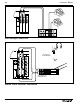
CENTURY SERIES LM Console Side Dimensions 0.75"/1 9mm & The following diagram illustrates the depth and height dimensions (from the side) for all Century LM consoles. All information per 35° T HEIGH KNOB May 5, 1997 Crest Consoles Engineering, /60mm 2.375" 2.25"/57mm m "/752m 29.625 2mm 1.25"/3 24.75"/ 717mm 28.0"/ 711mm 29.563" / 751mm 3mm 3.25"/8 m /260m m 10.25" 6.25"/159m /29mm 1.125" 2.437" 62mm 9.
MONITOR A LEFT MONITOR A RIGHT MONITOR B LEFT MONITOR B RIGHT EXT TB OUT BAL OUT INSERT RETURN INSERT SEND Master Section EXT TB IN RETURN 1 INSERT RETURN INSERT RETURN OSC IN INSERT RETURN INSERT SEND RETURN 2 BAL OUT INSERT SEND BAL OUT BAL OUT INSERT SEND BAL OUT RIGHT INSERT RETURN INSERT RETURN INSERT SEND BAL OUT RIGHT INSERT SEND INSERT RETURN INSERT RETURN BAL OUT LEFT INSERT SEND BAL OUT LEFT INSERT SEND BAL OUT LEFT BAL OUT LEFT INSERT RETURN INSERT SEND BAL OU
CENTURY SERIES LM LM USER-OPTIONS LM Consoles are shipped having standard configuration unless specified at time of order There are ways that the console configuration may be varied after manufacture. The items listed are internal options selected by gold jumper links. Default is marked with a line on the board and is usually pins 1&2 of the three pin header. In addition there are links for module function assignment. Take care to not disturb these when using USER OPTION links.
CENTURY SERIES LM Console Disassembly Though you shouldn’t have to disassemble the console, it is necessary to remove modules to change the jumper and switch settings associated with the internally selectable options. ALWAYS DISCONNECT THE POWER SUPPLY BEFORE OPENING THE CONSOLE! ONE•Releasing the armrest. Opening the Armrest To properly remove one or more modules, the black painted armrest must first be released. To do this, the two thumbscrews (see diagram at right) must be loosened from below.
LM Appendix B Glossary
CENTURY SERIES LM Glossary Balanced Insert Return See Insert Return Balanced Line In See Line Input Fader Used for final output control of an input/output channel except those sends selected pre fader. (Insert Output levels are not affected by the fader position.) Gain Control See Microphone Output Adjusts input gain for proper signal level on the input. To set the gain to the best position, make sure there is signal present at the input.
CENTURY SERIES LM Input Fader Mix Switch Oscillator On This switch activates circuitry that sums all input signals and assigns the summed signal to the Monitor A output. This signal is post fader. Switches on the internal (or external if connected) oscillator which is fixed at 1kHz . The oscillator only operates when the Talkback system is engaged. Lamp Dim Control Oscillator / Pink Noise In Controls the brightness of any 12 volt lighting devices attached to the XLR connectors on the light bar.
LM Return 1/2 These connectors accept a balanced signal which is delivered to the return master controls on the master section Return Level Controls Adjusts the level of return signals 1 and 2 in the output. These signals come from the Master Section. The center knob adjusts level while the outer knob adjusts panning within the stereo image. See Returns 1 & 2 on the Master Section description for more information.
LM Appendix C Schematics LOCATION DESCRIPTION LM 12 (MONO) INPUT MODULE LM 12 INPUT CONNECTOR 1 76D1753 03 LM 12 INPUT MAIN 2 76D1812 01 LM 20 / 8+4 INPUT CONNECTOR 3 76D1753 03 LM 20 / 8+4 INPUT MAIN 4 76D1830 01 LM MONO OUTPUT GROUP CONNECTOR 5 76D1824 02 "(LM 12 Groups 1-10, LM 8+4 & LM 20 Groups 9&10)" LM MONO GROUP MAIN 6 76D1823 02 STEREO / DUAL MONO OUTPUT GROUP MODULE LM DUAL MONO / STEREO GROUP CONNECTOR (1 OF 2) 7 76D1832 02 LM DUAL MONO / STEREO GROUP CONNECTOR (2
Crest Audio Inc. 100 Eisenhower Dr., Paramus NJ 07652 USA TEL: 201.909.8700 FAX: 201.909.8744 http://www.crestaudio.com Printed in USA *D7000002* LM Owners Manual Copyright © 1997 Crest Audio Inc. v. 2.