Installation and Operation Manual CW2900 Insert US ENVIRONMENTAL PROTECTION AGENCY PHASE II CERTIFIED WOOD INSERT Safety tested according to ULC S628, UL 737 and UL 1482 Standards by Intertek Testing Services www.century-heating.com Stove Builder International Inc. 250, rue de Copenhague, St-Augustin-de-Desmaures (Quebec) Canada G3A 2H3 Tel: (418) 878-3040 Fax: (418) 878-3001 This manual is available for free download on the manufacturer’s web site. It is a copyrighted document.
CW2900 Installation and Operation Manual THANK YOU FOR CHOOSING THIS CENTURY WOOD INSERT As one of North America’s largest and most respected wood stove and fireplace manufacturers, Stove Builder International takes pride in the quality and performance of all its products. We want to help you get maximum satisfaction as you use this product.
CW2900 Installation and Operation Manual Table of content PART A - OPERATION AND MAINTENANCE ................................. 6 1 Safety Information .............................................................................. 6 1.1 Summary of Operation and Maintenance Cautions and Warnings ......................... 6 2 General Information ........................................................................... 8 2.1 CW2900 Insert Specifications ......................................................
CW2900 Installation and Operation Manual 4.5 Fan Operation ...................................................................................................... 22 4.5.1 Building Different Fires for Different Needs ....................................................... 22 5 Maintaining Your Wood Heating System ....................................... 25 5.1 Insert Maintenance ............................................................................................... 25 5.1.1 Cleaning Door Glass .....
CW2900 Installation and Operation Manual 9.7.1 Why the Chimney Should Penetrate the Highest Heated Space ...................... 46 9.8 Supply of Combustion Air ..................................................................................... 47 9.8.1 Air Supply in Conventional Houses ................................................................... 47 Appendix 1: Blower Installation ............................................................
CW2900 Installation and Operation Manual PART A - OPERATION AND MAINTENANCE Please see Part B for installation instructions. 1 Safety Information 1.1 Summary of Operation and Maintenance Cautions and Warnings • HOT WHILE IN OPERATION, KEEP CHILDREN, CLOTHING AND FURNITURE AWAY. CONTACT MAY CAUSE SKIN BURNS. GLOVES MAY BE NEEDED FOR INSERT OPERATION. • USING AN INSERT WITH CRACKED OR BROKEN COMPONENTS, SUCH AS GLASS OR FIREBRICKS OR BAFFLES MAY PRODUCE AN UNSAFE CONDITION AND MAY DAMAGE THE INSERT.
CW2900 Installation and Operation Manual • DO NOT BURN: o o o o o o o o o GARBAGE OF ANY KIND, COAL OR CHARCOAL, TREATED, PAINTED OR COATED WOOD, PLYWOOD OR PARTICLE BOARD, FINE PAPER, COLORED PAPER OR CARDBOARD, SALT WATER DRIFTWOOD, MANUFACTURED LOGS CONTAINING WAX OR CHEMICAL ADDITIVES, RAILROAD TIES OR LIQUIDS SUCH AS KEROSCENE OR DIESEL FUEL TO START A FIRE. • THIS APPLIANCE SHOULD BE MAINTAINED AND OPERATED AT ALL TIMES IN ACCORDANCE WITH THESE INSTRUCTIONS.
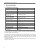
CW2900 Installation and Operation Manual 2 General Information 2.1 CW2900 Insert Specifications Fuel Type Cordwood Test Standards (safety) ULC S628, UL 737 and UL 1482 Test Standard (emissions) EPA Method 28 (40 CFR Part 60) Heating capacity range* 500 to 2100 sq. ft. (47 to 195 m2) Maximum heat output** (EPA test fuel) 32 200 BTU/h (9,4 kW/h) Maximum heat output** (natural hardwood fuel) 75 000 BTU/h (22 kW/h) Optimum efficiency 77,2 % Test Standard (efficiency) CSA B415.
CW2900 Installation and Operation Manual 9
CW2900 Installation and Operation Manual 2.2 Zone Heating and How to Make it Work for You Your new CW2900 wood insert is a space heater, which means it is intended to heat the area it is installed in, as well as spaces that connect to that area, although to a lower temperature. This is called zone heating and it is an increasingly popular way to heat homes or spaces within homes.
CW2900 Installation and Operation Manual 2.3 The Benefits of Low Emissions and High Efficiency The low smoke emissions produced by the special features inside the CW2900 firebox mean that your household will release up to 90 percent less smoke into the outside environment than if you used an older conventional stove. But there is more to the emission control technologies than protecting the environment. The smoke released from wood when it is heated contains about half of the energy content of the fuel.
CW2900 Installation and Operation Manual The door and glass gaskets are fibreglass which is spun from melted sand. Black gaskets have been dipped into a solvent-free solution. Disposal at a landfill is recommended. The door glass is a 5 mm thick ceramic material that contains no toxic chemicals. It is made of natural raw materials such as sand and quartz that are combined in such a way to form a high temperature glass.
CW2900 Installation and Operation Manual 3 Fuel 3.1 Materials That Should Not be Burned • GARBAGE OF ANY KIND, • COAL OR CHARCOAL, • TREATED, PAINTED OR COATED WOOD, • PLYWOOD OR PARTICLE BOARD, • FINE PAPER, COLORED PAPER OR CARDBOARD, • SALT WATER DRIFTWOOD • MANUFACTURED LOGS CONTAINING WAX OR CHEMICAL ADDITIVES • RAILROAD TIES • LIQUIDS SUCH AS KEROSCENE OR DIESEL FUEL TO START A FIRE 3.2 How to Prepare or Buy Good Firewood 3.2.
CW2900 Installation and Operation Manual wouldn’t hold a fire overnight unless they were fed large pieces of hardwood. That is no longer true. You can successfully heat your home by using the less desirable tree species and give the forest a break at the same time. 3.2.3 Log Length Logs should be cut at least 1” (25 mm) shorter than the firebox so they fit in easily. Pieces that are even slightly too long make loading the insert very difficult. The most common standard length of firewood is 16” (400 mm).
CW2900 Installation and Operation Manual Wood should be split to a range of sizes, from about 3” to 6” (75 mm to 150 mm) in cross section. Having a range of sizes makes starting and rekindling fires much easier. Often, the firewood purchased from commercial suppliers is not split finely enough for convenient stoking. It is sometimes advisable to resplit the wood before stacking to dry. 3.2.5 How to Dry Firewood Firewood that is not dry enough to burn is the cause of most complaints about wood inserts.
CW2900 Installation and Operation Manual 3.2.
CW2900 Installation and Operation Manual 4 Operating Your Insert 4.1 The Use of a Fire Screen This insert has been tested for use with an open door in conjunction with a fire screen (AC01315 sold separately). Make sure the fire screen is properly secured on the insert to avoid any risk of sparks damaging your flooring. When the fire screen is in use, do not leave the insert unattended so that you can respond promptly in the event of smoke spillage into the room.
CW2900 Installation and Operation Manual 4.3.1 Conventional Fire Starting The conventional way to build a wood fire is to bunch up 5 to 10 sheets of plain newspaper and place them in the firebox. Next, place 10 or so pieces of fine kindling on the newspaper. This kindling should be very thin; less than 1” (25 mm). Next, place some larger kindling pieces on the fine kindling. Open the air control fully and light the newspaper.
CW2900 Installation and Operation Manual 4.3.3 Two Parallel Logs Place two spit logs in the firebox. Place a few sheets of twisted newspaper between the logs. Now place some fine kindling across the two logs and some larger kindling across those, log cabin style. Light the newspaper. 4.3.4 Using Fire Starters Many people like to use commercial fire starters instead of newspaper. Some of these starters are made of sawdust and wax and others are specialized flammable solid chemicals.
CW2900 Installation and Operation Manual IF YOU MUST OPEN THE DOOR WHILE THE FUEL IS FLAMING, OPEN THE AIR CONTROL FULLY FOR A FEW MINUTES, THEN UNLATCH AND OPEN THE DOOR SLOWLY. 4.4.2 Ash Removal Ash should be removed from the firebox every two or three days of full time heating. Do not let the ash build up in the firebox because it will interfere with proper fire management.
CW2900 Installation and Operation Manual 4.4.4 Firing Each New Load Hot Place the new load of wood on and behind the charcoal, and not too close to the glass. Close the door and open the air control fully. Leave the air control fully open until the firebox is full of flames, the wood has charred to black and its edges are glowing red.
CW2900 Installation and Operation Manual 4.5 Fan Operation Allow the insert to reach operating temperature (approximately one hour), before turning on the fan, since increased airflow from the fan will remove heat and affect the start-up combustion efficiency. NOTE: ENSURE THE FAN CORD IS NOT IN CONTACT WITH ANY SURFACE OF THE INSERT TO PREVENT ELECTRICAL SHOCK OR FIRE DAMAGE. DO NOT RUN CORD BENEATH THE INSERT.
CW2900 Installation and Operation Manual more. Small fires like this are a good time to use softer wood species so there will be less chance of overheating the house. 4.5.1.2 Long Lasting Low Output Fires Sometimes you will want to build a fire to last up to eight hours, but don’t need intense heat. In this case use soft wood species and place the logs compactly in the firebox so the pieces are packed tightly together.
CW2900 Installation and Operation Manual The table below provides a very general indication of the maximum burn cycle times you are likely to experience, based on firebox volume. FIREBOX VOLUME <1.5 cubic feet 1.5 c.f. to 2.0 c.f 2.0 c.f. to 2.5 c.f. 2.5 c.f. to 3.0 c.f. >3.0 c.f. MAXIMUM BURN TIME 3 to 5 hours 5 to 6 hours 6 to 8 hours 8 to 9 hours 9 to 10 hours Long burn times are not necessarily an indication of efficient insert operation.
CW2900 Installation and Operation Manual 5 Maintaining Your Wood Heating System 5.1 Insert Maintenance Your new insert will give many years of reliable service if you use and maintain it correctly. Some of the internal components of the firebox, such as firebricks, baffles and air tubes, will wear over time under intense heat. You should always replace defective parts with original parts (see Appendix 8: Exploded Diagram and Parts List).
CW2900 Installation and Operation Manual 5.1.2 Replacing the Door Gasket It is important to maintain the gasket in good condition. After a year or more of use, the door gasket will compress and become hard, which may allow air to leak past it. You can test the condition of the door gasket by closing and latching the door on a strip of paper. Test all around the door. If the paper slips out easily anywhere, it is time to replace the gasket.
CW2900 Installation and Operation Manual edge of the glass down onto the gasket, taking care that it is perfectly centred on the gasket. Peel off more of the backing and rotate the glass and press the next section onto the gasket. Do not stretch the gasket as you place it. Continue until you get to the start and trim the gasket to length. Now pinch the gasket to the glass in a U shape, all around the glass. Reinstall the glass, being careful to centre the glass in the door. Do not over-tighten the screws.
CW2900 Installation and Operation Manual 5.2.3 Cleaning the Chimney Chimney cleaning can be a difficult and dangerous job. If you don’t have experience cleaning chimneys, you might want to hire a professional chimney sweep to clean and inspect the system for the first time. After having seen the cleaning process, you can decide if it is a job you would like to take on. The most common equipment used are fibreglass rods with threaded fittings and stiff plastic brushes.
CW2900 Installation and Operation Manual PART B - INSTALLATION 6 Pre-Installation Masonry Fireplace Requirements The masonry fireplace must meet the minimum requirements found in the building code enforced locally, or the equivalent for a safe installation. Contact your local Building Inspector for requirements in your area. An inspection of the fireplace should include the following: 1.
CW2900 Installation and Operation Manual 3. CHIMNEY CAPS: Mesh type chimney caps must have provision for regular cleaning, or the mesh should be removed to eliminate the potential of plugging. 4. ADJACENT COMBUSTIBLES: The fireplace should be inspected to make sure that there is adequate clearance to combustibles, both exposed combustibles to the top, side, and front as well as concealed combustibles, in the chimney and mantle area.
CW2900 Installation and Operation Manual 7 Safety Information 7.1 Summary of Installation Cautions and Warnings • THE INFORMATION GIVEN ON THE CERTIFICATION LABEL AFFIXED TO THE APPLIANCE ALWAYS OVERRIDES THE INFORMATION PUBLISHED, IN ANY OTHER MEDIA (OWNER’S MANUAL, CATALOGUES, FLYERS, MAGAZINES AND/OR WEB SITES). • MIXING OF APPLIANCE COMPONENTS FROM DIFFERENT SOURCES OR MODIFYING COMPONENTS MAY RESULT IN HAZARDOUS CONDTIONS. WHERE ANY SUCH CHANGES ARE PLANNED, STOVE BUILDER INTERNATIONAL INC.
CW2900 Installation and Operation Manual This insert must be installed with a continuous chimney liner of 6” diameter extending from the insert to the top of the chimney. The chimney liner must conform to the Class 3 requirements of CAN/ULC-S635, Standard for Lining Systems for Existing Masonry or Factory-built Chimneys and Vents, or CAN/ULC-S640, Standard for Lining Systems for New Masonry Chimneys.
CW2900 Installation and Operation Manual 8 Clearances to Combustible Material The clearances shown in this section have been determined by test according to procedures set out in safety standards ULC S628 (Canada), UL1482 (U.S.A.) and UL737 (U.S.A.). When the insert is installed so that its surfaces are at or beyond the minimum clearances specified, combustible surfaces will not overheat under normal and even abnormal operating conditions.
CW2900 Installation and Operation Manual 8.3 Compliance of a Combustible Mantel Shelf To ensure compliance of an existing mantel shelf or to install a combustible mantel shelf, refer to table and figure below. For example, a mantel shelf with a 8’’ depth (203 mm) ((X) value) must be installed at least 22" (559 mm) ((I) value) above the top of the insert (see figure below). Different mantel shelf dimensions are listed in the following table.
CW2900 Installation and Operation Manual 8.4 Positioning the Unit It is necessary to have a floor protection made of non-combustible materials that meets the measurements specified in the FLOOR PROTECTION table in Section 8.5. To determine the need to add floor protection (D) beyond the hearth extension, you must do the following calculation using the data in the Data for floor protection calculation table of this section: D = B - (A - C).
CW2900 Installation and Operation Manual If the extension of the masonry hearth is raised at least 4" from the floor protection, a noncombustible material without an R factor is sufficient. If non-combustible material floor protection needs to be added in front of and level with the hearth extension of the masonry fireplace, an R factor equal to or greater than 2.00 is required.
CW2900 Installation and Operation Manual The use of an R value is convenient when more than one material is going to be used in the hearth extension to cover the combustible surface. This is because R values are additive, whereas K values are not. There are two ways to calculate the R factor of the floor protection. First, by adding the Rvalues of materials used, or by the conversion if the K factor and thickness of the floor protection are given.
CW2900 Installation and Operation Manual Thermal Characteristics of Common Floor Protection Materials* MATERIAL Micore® 160 Micore® 300 Durock® Hardibacker® Hardibacker® 500 Wonderboard® Cement mortar Common brick Face brick Marble Ceramic tile Concrete Mineral wool insulation Limestone Ceramic board (Fibremax) Horizontal still air** (1/8") CONDUCTIVITY (k) PER INCH 0.39 0.49 1.92 1.95 2.3 3.23 5.00 5.00 9.00 14.3 – 20.00 12.5 1.050 0.320 6.5 0.450 0.135 RESISTANCE (R) PER INCH THICKNESS 2.54 2.06 0.
CW2900 Installation and Operation Manual When installed as an extended insert, the front edge of the air jacket will be installed flush with the fireplace facing. Otherwise the unit can be moved back as much as 2 1/4" (57 mm) or any position in between. The position chosen will depend on your own preference for most installations, your current configuration, the compliance with the preceding installation instructions and compliance with the building code requirements.
CW2900 Installation and Operation Manual 8.
CW2900 Installation and Operation Manual MINIMUM MASONRY OPENING CLEARANCES F 16" (406 mm) J 23 3/8" (594 mm) G 12" (305 mm) K 28 7/8" (733 mm)** H 20" (508 mm) L 15 7/8" (403 mm) I 22" (559 mm)* MAXIMUM THICKNESS O 12" (305 mm) P 1" (25 mm) FLOOR PROTECTION CANADA USA B 18’’ (457 mm) – Note1 16’’ (406 mm) – Note 1 M 8’’ (203 mm) N/A (Canada only) N N/A (USA only) 8’’ (203 mm) Minimum floor to ceiling clearance: 84’’ (213 cm) * For a 8" (203 mm) mantel shelf. See Section 8.
CW2900 Installation and Operation Manual 9 The Venting System 9.1 General The venting system, made up of the chimney and the liner inside the chimney, acts as the engine that drives your wood heating system. Even the best insert will not function safely and efficiently as intended if it is not connected to a suitable chimney and liner system. The heat in the flue gases that pass from the insert into the chimney is not waste heat.
CW2900 Installation and Operation Manual 9.3 Suitable Chimneys Your wood insert will provide optimum efficiency and performance when connected to a 6inch diameter chimney liner. The connection to a chimney having a diameter of at least 5 inches (Canada only) is permitted, if it allows the proper venting of combustion gases and that such application is verified and authorized by a qualified installer. Otherwise, the diameter of the flue should be 6 inches.
CW2900 Installation and Operation Manual 9.5 Chimney Liner Installation The preferred methods for installing the chimney liner are found in Section 9.5.1. Use a liner offset adapter (Section 9.5.2) only as a last resort. 9.5.1 If the chimney liner does align with the insert’s flue outlet, you have two options A) Install the chimney liner starter adapter, provided with the chimney liner. Follow the chimney liner starter adapter manufacturer's instructions.
CW2900 Installation and Operation Manual B) Your dealer may offer a liner fastening system (AC02006), sold separately. Follow the installation instructions provided with the liner fastening system. 9.5.2 If the chimney liner does not align with the insert’s flue outlet You can install a liner offset adapter (AC01370), which is sold separately. Please note that an offset adaptor reduces the free flow of exhaust gases and may result in smoke roll-out from the insert when it’s door is opened for loading.
CW2900 Installation and Operation Manual 9.6 Minimum Height Chimney The top of the chimney should be tall enough to be above the air turbulence caused when wind blows against the house and its roof. The chimney must extend at least 1 m (3 ft.) above the highest point of contact with the roof, and at least 60 cm (2 ft.) higher than any roof line or obstacle within a horizontal distance of 3 m (10 ft.). 9.
CW2900 Installation and Operation Manual 9.8 Supply of Combustion Air In Canada, wood inserts are not required to have a supply of combustion air from outdoors because research has shown that these supplies do not give protection against house depressurization and may fail to supply combustion air during windy weather. However, to protect against the risk of smoke spillage due to house depressurization, a carbon monoxide (CO) detector/alarm is required in the room in which the insert is installed.
CW2900 Installation and Operation Manual Appendix 1: Blower Installation Position the blower assembly under the ash lip and push it against the insert. Fasten the blower assembly with 2 Torx® type screws provided with the insert, using a ratchet and a Torx® bit.
CW2900 Installation and Operation Manual Appendix 2: Installing the Adapter for Fresh Air Kit (AC01298) Note: Only remove the knock-out that will be connected to the fresh air inlet. To install a fresh air intake to the insert, the purchase of accessory AC01298 adapter is required. Using pliers, remove the rectangular knock-out plate (A) located on the left or right side of the convection air jacket. Choose the side that is best for your installation.
CW2900 Installation and Operation Manual Appendix 3: Faceplate Installation Remove the faceplate panels from their box and follow the installation instructions below; Contents: (4) - #10-24 x 1/2" bolt (4) - #10-24 hex nut (2) – 1/2" x 3" spring Place the faceplate panels with the finished side down on a flat, soft, non-abrasive surface. Line up the holes from of the upper panel with the holes of side panel and secure them together using the bolts and nuts provided.
CW2900 Installation and Operation Manual Once the faceplate is assembled, align the notches, located at the top of each side of the faceplate opening, with the top of the insert and slide the assembly toward the front of the insert (see DETAIL A). Center the insert into the fireplace opening. Adjust its height using the leveling bolts on each side of the convection air jacket box until the faceplate is properly seated on the floor of the hearth extension.
CW2900 Installation and Operation Manual Appendix 4: Top Surround and Mantel Shelf Heat Shield Installation (AC01317) When a heat shield is installed, you can reduce the clearances to the mantle shelf and the top surround as followed (refer to Section 8.3 Compliance of a Combustible Mantel Shelf for additional details).
CW2900 Installation and Operation Manual Appendix 5: Installing the Fire Screen (AC01315) Open the door. Hold the fire screen by the two handles and bring it close to the door opening. Lean the upper part of the fire screen against the top door opening making sure to insert the top fire screen brackets behind the primary air deflector as in (DETAIL A). Lift the fire screen upwards and push the bottom part towards the stove then let the fire screen rest on the bottom of the door opening.
CW2900 Installation and Operation Manual Appendix 6: Installation of Secondary Air Tubes and Baffle 1. Starting with the rear tube, lean and insert the right end of the secondary air tube into the rear right channel hole. Then lift and insert the left end of the tube into the rear left channel. 2. Align the notch in the left end of the tube with the key of the left air channel hole. Using a « Wise grip » hold the tube and lock it in place by turning the tube as shown in DETAIL A.
CW2900 Installation and Operation Manual Note that any secondary air tubes (A) can be replaced without removing the baffle board (B). Important Notes: The air tubes are identified for placement as follows: Model Type of tube CW2900 Insert Front ► 30 holes of 0.147" Middle front ► 30 holes of 0.136’’ Middle rear ► 20 holes of 0.128’’ Rear ► 15 holes of 0.
CW2900 Installation and Operation Manual Appendix 7: Removal Instructions For the purpose of inspecting the insert itself or the fireplace, your insert may need to be removed. To remove your insert follow these instructions: 56 Remove the faceplate retainer springs (B) holding the faceplate (C) to the Insert. Remove the faceplate by pulling it towards you. Remove the blower assembly (D). Remove the three screws securing the pipe connector (A).
CW2900 Installation and Operation Manual Appendix 8: Exploded Diagram and Parts List 57
CW2900 Installation and Operation Manual IMPORTANT: THIS IS DATED INFORMATION. When requesting service or replacement parts for your stove, please provide the model number and the serial number. We reserve the right to change parts due to technology upgrade or availability. Contact an authorized dealer to obtain any of these parts. Never use substitute materials. Use of non-approved parts can result in poor performance and safety hazards.
CW2900 Installation and Operation Manual # 35 36 37 38 39 40 41 42 43 44 45 46 47 48 49 50 51 Item PL65606 PL65605 PL34052 SE45557 AC01317 SE65591 30472 21387 PL65505 29010 PL36021 PL36103 PL65514 PL65515 PL65516 PL65517 21388 Description RIGHT DECORATIVE PANEL LEFT DECORATIVE PANEL LINER FIXATION BRACKET INSTRUCTION MANUEL KIT FOR CW2900 INSERT HEAT SHIELD FOR SURROUND / SHELF 3 PIECE FACEPLATE KIT 32'' X 50'' SPRING 1/2'' OUTSIDE DIA.
CW2900 Installation and Operation Manual CENTURY HEATING LIMITED LIFETIME WARRANTY The warranty of the manufacturer extends only to the original consumer purchaser and is not transferable. This warranty covers brand new products only, which have not been altered, modified nor repaired since shipment from factory. Proof of purchase (dated bill of sale), model name and serial number must be supplied when making any warranty claim to your CENTURY dealer. This warranty applies to normal residential use only.