
Use and Care Manual


507713-01 Page 13 of 32Issue 1623
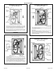
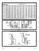
Horizontal Position
HORIZONTAL RIGHT POSITION
Side Vent Discharge
Figure 22
HORIZONTAL LEFT POSITION
Side Vent Discharge
Figure 20
• Cut combustion air inducer tubing from 9” to 7” to avoid interference
with inducer motor.
• Disconnect pressure switch hose from barbed tting on the pressure
switch assembly. Remove pressure switch assembly (1 screw) and cut
wire tie to free pressure switch wires. Reinstall pressure switch on the
other side of orice plate and reconnect pressure switch hose.
• Resecure pressure seitch wires: Either pull excess wires through the
blower compartment and secure using supplied wire tie, or coil excess
wire and secure to the gas manifold.
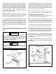
HORIZONTAL RIGHT POSITION
Top Vent Discharge
Figure 21
• Gas supply piping must be brought into the unit from the bottom in order
to accommodate the ue pipe.
• Cut combustion air inducer tubing from 9” to 8” to avoid interference with
inducer motor.
• Remove make-up box assembly (2 screws) and cut wire tie to free make-
up box wires. Reinstall make-up box on other side of cabinet.
• Resecure make-up box wires: Either pull excess wires through the blower
compartment and secure using supplied wire tie, or coil excess wire and
secure to the gas manifold.
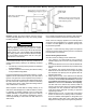
HORIZONTAL LEFT POSITION
Top Vent discharge
Figure 19
• Disconnect pressure switch hose from barbed tting on the pressure
switch assembly. Remove pressure switch assembly (1 screw) and cut
wire tie to free pressure switch wires. Reinstall pressure switch on the
other side of orice plate and reconnect pressure switch hose.
• Resecure pressure seitch wires: Either pull excess wires through the
blower compartment and secure using supplied wire tie, or coil excess
wire and secure to the gas manifold.