INSTALLATION INSTRUCTIONS GUH80C Warm Air Gas Furnace Upflow / Horizontal Left and Right Air Discharge This manual must be left with the homeowner for future reference. This is a safety alert symbol and should never be ignored. When you see this symbol on labels or in manuals, be alert to the potential for personal injury or death. WARNING CAUTION Improper installation, adjustment, alteration, service or maintenance can cause property damage, personal injury or loss of life.
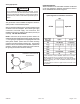
A80UH1E & 80G1UHE Unit Dimensions - inches (mm) NOTE - C5 and D5 size units installed in upflow applications that require air volumes of 1800 cfm (850 L/s or greater must have one of the following: 1. Single side return air with transition, to accommodate 20 x 25 x 1 in. (508 x 635 x 25 mm) air filter. 2. Single side return air with optional RAB Return Air Base 3. Bottom return air. 4. Return air from both sides. 5. Bottom and one side return air.
Expanded View Figure 1 506842-01 Issue 1132 Page 3 of 42
GUH80C Gas Furnace The GUH80C gas furnace is shipped ready for installation in the upflow or horizontal right position (for horizontal left position the combustion air pressure switch must be moved). The furnace is shipped with the bottom panel in place. The bottom panel must be removed if the unit is to be installed in horizontal or upflow applications with bottom return air. The furnace is equipped for installation in natural gas applications.
Temperature Rise NOTE: Furnace must be adjusted to obtain a temperature rise within the range specified on the unit nameplate. Failure to do so may cause erratic limit operation and may result in premature heat exchanger failure. This furnace must be installed so that its electrical components are protected from water.
General These instructions are intended as a general guide and do not supersede local codes in any way. Consult authorities having jurisdiction before installation. In addition to the requirements outlined previously, the following general recommendations must be considered when installing one of these furnaces: • • • • Place the furnace as close to the center of the air distribution system as possible. The furnace should also be located close to the chimney or vent termination point.
All gas fired appliances require air for the combustion process. If sufficient combustion air is not available, the furnace or other appliances will operate inefficiently and unsafely. Enough air must be provided to meet the needs of all fuel burning appliances and appliances such as exhaust fans which force air out of the house. When fireplaces, exhaust fans, or clothes dryers are used at the same time as the furnace, much more air is necessary to ensure proper combustion and to prevent a downdraft.
When ducts are used, they shall be of the same cross sectional area as the free area of the openings to which they connect. The minimum dimension of rectangular air ducts shall be no less than 3 inches (75 mm). In calculating free area, the blocking effect of louvers, grilles, or screens must be considered.
Setting Equipment Upflow Applications Allow for clearances to combustible materials as indicated on the unit nameplate. Minimum clearances for closet or alcove installations are shown in Figure 8. WARNING Do not install the furnace on its front or its back. Do not connect the return air ducts to the back of the furnace. Doing so will adversely affect the operation of the safety control devices, which could result in personal injury or death.
Return Air - Upflow Applications Return air can be brought in through the bottom or either side of the furnace installed in an upflow application. If the furnace is installed on a platform with bottom return, make an airtight seal between the bottom of the furnace and the platform to ensure that the furnace operates properly and safely. The furnace is equipped with a removable bottom panel to facilitate installation.
Removing the Bottom Panel Remove the two screws that secure the bottom cap to the furnace. Pivot the bottom cap down to release the bottom panel. Once the bottom panel has been removed, reinstall the bottom cap. See Figure 11. Removing the Bottom Panel Horizontal Applications The furnace can be installed in horizontal applications. Order horizontal suspension kit (51W10) from Allied Air, or use equivalent suspension method. Allow for clearances to combustible materials as indicated on the unit nameplate.
Horizontal Application Unit installed on Platform Table 1 Duct System Use industry approved standards (such as those published by Air Conditioning Contractors of America or American Society of Heating, Refrigerating and Air Conditioning Engineers) to size and install the supply and return air duct system. This will result in a quiet and low static system that has uniform air distribution. Figure 14 NOTE: Do not operate the furnace in the heating mode with an external static pressure that exceeds 0.
Venting A 4 inch diameter flue transition is factory installed on the combustion air inducer outlet of all models. Figure 16 shows the combustion air inducer as shipped from the factory. Mounting Screws Location 1. Remove the four mounting screws (Figure 15) which secure the combustion air inducer / pressure switch assembly to the orifice plate. Lift the assembly and rotate it 90° clockwise or counter clockwise to either the 3 o’clock position. Resecure with four secrews. Gasket should be left in place. 2.
HORIZONTAL LEFT POSITION Top Vent discharge • • HORIZONTAL RIGHT POSITION Top Vent Discharge Disconnect pressure switch hose from barbed fitting on the pressure switch assembly. Remove pressure switch assembly (1 screw) and cut wire tie to free pressure switch wires. Reinstall pressure switch on the other side of orifice plate and reconnect pressure switch hose.
These series units are classified as fan assisted Category I furnaces when vertically vented according to the latest edition of National Fuel Gas Code (NFPA 54 / ANSI Z223.1) in the USA. A fan assisted Category I furnace is an appliance equipped with an integral mechanical means to either draw or force combustion products through the combustion chamber and/or heat exchanger. This unit is not approved for use with horizontal venting. NOTE: Use these instructions as a guide. They do not supersede local codes.
Common Venting Using Tile Lined Interior Masonry Chimney and Combined Vent Connector NOTE: Refer to provided venting tables for installations. NOTE: The chimney must be properly sized per provided venting tables or lined with listed metal lining system. Figure 25 DO NOT insulate the space between the liner and the chimney wall with puffed mica or any other loose granular insulating material.
5. Multiple appliance vents - The flow area of the largest section of vertical vent or chimney shall not exceed 7 times the smallest listed appliance categorized vent area, drafthood outlet area or flue collar area unless designed according to approved engineering methods. 6. The entire length of single wall metal vent connector shall be readily accessible for inspection, cleaning, and replacement. 7.
Capacity of Type B Double Wall Vents with Type B Double Wall Connectors Serving a Single Category I Appliance NOTE: Single appliance venting configureations with zero lateral lengths are assumed to have no elbows in the vent system. For all other vent configurations, the vent system is assumed to have two 90 ° elbows. For each additional 90° elbow or equivalent (for example two 45° elbows equal one 90° elbow) beyond two, the maximum capacity listed in the venting table should be reduced by 10 percent (0.
Capacity of Type B Double Wall Vents with Single Wall Metal Connectors Serving a Single Category I Appliance NOTE: Single appliance venting configureations with zero lateral lengths are assumed to have no elbows in the vent system. For all other vent configurations, the vent system is assumed to have two 90 ° elbows. For each additional 90° elbow or equivalent (for example two 45° elbows equal one 90° elbow) beyond two, the maximum capacity listed in the venting table should be reduced by 10 percent (0.
Vent Connector Capacity Type B Double Wall Vents with Type B Double Wall Connectors Serving Two or More Category I Appliances Table 5 Common Vent Capacity Type B Double Wall Vents with Type B Double Wall Connectors Serving Two or More Category I Appliances Table 6 Page 20 of 42 Issue 1132 506842-01
Vent Connector Capacity Type B Double Wall Vents with Single Wall Metal Connectors Serving Two or More Category I Appliances NOTE: Single appliance venting configureations with zero lateral lengths are assumed to have no elbows in the vent system. For all other vent configurations, the vent system is assumed to have two 90 ° elbows.
Removal of the Furnace from Common Vent In the event that an existing furnace is removed from a venting system commonly run with separate gas appliances, the venting system is likely to be too large to properly vent the remaining attached appliances. Conduct the following test while each appliance is operating and the other appliances (which are not operating) remain connected to the common venting system.
Gas Piping CAUTION If a flexible gas connector is required or allowed by the authority that has jurisdiction, black iron pipe shall be installed at the gas valve and extend outside the furnace cabinet. The flexible connector can then be added between the black iron pipe and the gas supply line. Gas Supply 1. This unit is shipped standard for left or right side installation of gas piping (or top entry in horizontal applications). Connect the gas supply to the piping assembly. 2.
NOTE: BLACK IRON PIPE ONLY TO BE ROUTED INSIDE OF CABINET Figure 26 Horizontal Applications Possible Gas Piping Configurations NOTE: BLACK IRON PIPE ONLY TO BE ROUTED INSIDE OF CABINET Figure 27 Page 24 of 42 Issue 1132 506842-01
Leak Check After gas piping is completed, carefully check all piping connections (factory and field installed) for gas leaks. Use a leak detecting solution or other preferred means. NOTE: If emergency shutoff is necessary, shut off the main manual gas valve and disconnect the main power to the furnace. The installer should properly label these devices. The unit is equipped with a field make-up box on the left hand side of the cabinet.
Before connecting the thermostat, check to make sure the wires will be long enough for servicing at a later date. Make sure that thermostat wire is long enough to facilitate future removal of blower for service. Complete the wiring connections to the equipment. Use the provided unit wiring diagram and the field wiring diagram shown in Figure 33. Use 18 gauge wire or larger that is suitable for Class II rating for thermostat connections.
Wiring Diagram 045A3M 070B3M 090B4M 090C5M 110C5M 135D5M GUH80C Figure 32 506842-01 Issue 1132 Page 27 of 42
Typical Field Wiring Diagram Figure 33 Integrated Control (Automatic Hot Surface Ignition System) Figure 34 Page 28 of 42 Issue 1132 506842-01
6. Move switch on gas valve to OFF. Do not force. See Figure 35. 7. Wait five minutes to clear out any gas. If you then smell gas, STOP! Immediately call your gas supplier from a neighbor’s phone. Follow the gas supplier’s instructions. If you do not smell gas go to next step. Unit Start-UP FOR YOUR SAFETY READ BEFORE LIGHTING UNIT. WARNING Do not use this furnace if any part have been underwater.
Heating Sequence Of Operation (Figure 36) 1. When thermostat calls for heat, combustion air blower starts. 2. Combustion air pressure switch proves blower operation. Switch is factory set and requires no adjustment. 3. After a 15 second prepurge, the hot surface ignitor energizes. 4. After a 20 second ignitor warm-up period, the gas valve solenoid opens. A 4 second trial for ignition period begins. 5. Gas is ignited, flame sensor proves the flame, and the combustion process continues. 6.
High Altitude Units may require manifold pressure adjustment at altitudes above 2000 ft. In some cases, it is necessary to change the pressure switch to ensure proper combustion. In all cases (natural gas and LP/propane gas), maximum line pressure is 13.0” w.c. Refer to Table 12. IMPORTANT For Safety, shut unit off and remove manometer as soon as an accurate reading has been obtained. Take care to replace pressure tap plug.
Fan Control The fan on time of 45 seconds is not adjustable. The heat fan off delay (amount of time that the blower operates after the heat demand has been satisfied) may be adjusted by changing the jumper position across the five pins on the integrated control. The unit is shipped with a factory fan off delay setting of 90 seconds. The fan off delay affects comfort and is adjustable to satisfy individual applications.
Blower Data GUH80C GUH80C045A3M PERFORMANCE (Less Filter) Air Volume / Watts at Various Blower Speeds External MediumMediumStatic High Medium Low High Pressure cfm Watts cfm Watts cfm Watts cfm Watts in. w.c. w 0.00 1345 265 1380 340 1155 1255 165 245 1150 185 895 975 115 105 995 120 270 1120 175 950 120 880 105 0.10 1345 13 900 125 0.20 1290 260 1080 205 825 1320 360 285 1190 1080 190 805 380 105 120 110 1290 295 1055 200 875 135 750 0.30 1220 310 385 1010 1120 205 280 1015 0.
Blower Data GUH80C GUH80C090C5M PERFORMANCE (Less Filter) Air Volume / Watts at Different Blower Speeds Bottom Return Air, Side Return Air with Optional Return Single Side Return Air í Air volumes in bold require field External fabricated transition to accommondate 20 x 25 x 1 in. air filter Static Air Base, Return Air from Both Sides or Return Air from Bottom and One Side. in order to maintain proper air velocity. Pressure Medium Medium High Medium-High Medium-Low Low High Medium-High Medium-Low Low in.
Service WARNING WARNING The blower access panel must be securely in place when the blower and burners are operating. Gas fumes, which could contain carbon monoxide, can be drawn into living space resulting in personal injury or death. ELECTRICAL SHOCK, FIRE, OR EXPLOSION HAZARD. Failure to follow safety warnings exactly could result in dangerous operation, serious injury, death or property damage. Filters Filters are installed external to the unit. Filters should be inspected monthly.
Cleaning the Heat Exchanger and Burners NOTE: Use papers or protective covering in front of the furnace during cleaning. 1. Turn off both electrical and gas power supplies to furnace. 2. Remove flue pipe and top cap (some applications top cap can remain) from the unit. 3. Label the wires from gas valve, rollout switches, primary limit switch and make-up box then disconnect them. 4. Remove the screws that secure the combustion air inducer/pressure switch assembly to the collector box.
9. Remove screws from both sides, top and bottom of vestibule panel. 10. Remove heat exchanger. It may be necessary to spread cabinet side to allow more room. If so, remove five screws from the left side or right side of cabinet. See Figure 40. 11. Backwash using steam. Begin from the bumer opening on each clam. Steam must not exceed 275°F. 12. To clean burners, run a vacuum cleaner with a soft brush attachment over the face of burners.
PLANNED SERVICE The following items should be checked during an annual inspection. Power to the unit must be shut off for the service technician’s safety. FAILURE CODES Fresh air grilles and louvers (on the unit and in the room where the furnace is installed) - Must be open and unobstructed to provide combustion air. Burners - Must be inspected for rust, dirt, or signs of water. Vent pipe - Must be inspected for signs of water, damaged or sagging pipe, or disconnected joints.
REPAIR PARTS LIST The following repair parts are available through independent Allied Air dealers. When ordering parts, include the complete furnace model number listed on the CSA International nameplate — Example: GUH80C045A3M. All service must be performed by a licensed professional installer (or equivalent), service agency, or gas supplier.
START-UP & PERFORMANCE CHECK LIST UNIT SET UP Page 40 of 42 Issue 1132 506842-01
UNIT OPERATION 506842-01 Issue 1132 Page 41 of 42
REQUIREMENTS for COMMONWEALTH of MASSACHUSETTS Modifications to NFPA-54, Chapter 10 Revise NFPA-54 section 10.8.