
Instruction manual


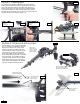


Remove the 3
socket head cap
screws to open the
gearbox in order to
grease the gears.
8.1
Section 7: Landing gear
7.1
7.2
7.3
All components for installing landing gear are included with the
landing gear bag. Attach the plastic U shaped struts to the bottom
of the main frame and insert the metal skids when aligned (7.1).
Bolt the landing gear to the main frame using provided hardware
(7.2). Attach the skids only when helicopter will sit level using the
provided set screws and CA glue (7.3). At the end of this section the
helicopter should be able to stand upright (7.4).
8.2
8.3
M3x16 socket head cap
screws (4)
M3 Locknut (4)
M3x4 socket head set
screws (4)
CA Glue
M3x30 socket head
cap screws (2)
M3 Locknut (2)
M3x16 socket head
cap screws (2)
M3 Locknut (2)
Place a small dab of gear grease
(synthetic hydrogen grease)
between the two plastic gears.
Section 8: Tail boom & drive system
The tail section (8.1) is completely assembled
and only requires to be attached to the main
frame (use a small amount of gear grease
inside the tail gearbox). Slide the tail boom
into the aft section of the main frame with the
tail rotor on the right side of the helicopter
(8.2) twisting slightly until the notches in the
tail boom align with the standoffs on the inside
of the main frame. Once installed, the drive
system should be complete and the main/tail
blades should rotate when the main gear is
turned. Attach the tail blades to the tail blade
grips (8.3) using the hardware provided.
Note:
7.4
White coupler located
inside the upper frames
8