CT63 E Terminal User Manual Revision 1.
Important information This technical description contains important information for start up and use of the CT63 E Terminal. Read it carefully before you start working with the CT63 E Terminal. The warranty will be void should damage occur due to non-compliance with these instructions for use. We cannot accept any responsibility for consequential loss. We cannot be held responsible for material loss or personal injury that is due to incompetent use or non-compliance with the safety instructions.
not clearly states which electric data is valid for a component or a module, how to wire the device, which external components or additional devices can be connected or which parameters these components are allowed to have, a specialist must be contacted. Before putting a device into operation, it has to be clarified, whether this device or module is meant for the field of application. In case of doubt ask specialists or the manufacturer of the device.
Table of Contents Important information ......................................................................................................................... 2 Safety Instructions .............................................................................................................................. 2 1 2 3 Mechanical Description ................................................................................................................. 7 1.1 Overview .....................................
.1.3 Connections of components to CT63 E Terminal .............................................................. 20 5.1.4 Network and Subscription .............................................................................................. 21 5.2 How to install the modem..................................................................................................... 21 5.2.1 Power supply ...........................................................................................................
Table Overview Table Table Table Table Table Table Table Table Table Table 1: Pin Description .................................................................................................................... 10 2: RJ11 Pin and Signals Description ........................................................................................... 10 3: Recommended antenna parameters ......................................................................................
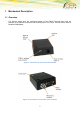
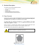
1 Mechanical Description 1.1 Overview The pictures below show the mechanical design of the CT63-E Terminal along with the positions of the different connectors and mounting holes. The CT63-E Terminal case is made of durable PC/ABS plastic.
Please note the following: Mounting holes positioned at two of the corners make it possible to securely bolt the modem into your application. Keypad, display, microphone, speaker and battery are not part of the modem. The SIM card is mounted in the modem, accessible by the user under a lid without any tools. The pins and electrical characteristics or the modem’s various connectors are described in “2. Electrical Description” Information about the antenna connector is found in “2.
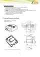
2 Electrical Description The modem uses the following standard connectors: RJ11 6-way (power connector) Mini USB SIM card reader FME male coaxial jack (antenna connector) Sub-D female socket, 9 pin (RS232 serial port) 2.1 Power Connector An RJ11 6-way connector, as shown and described below, serves as a means of supplying and controlling DC power to the modem. It is necessary to connect an external power supply, since the available power on the USB port is not sufficient to run the modem.
PIN Description 1 VCC 2 - 3 EMERG_OFF 44 TO_IN 5 - 6 GND Table 1: Pin Description PIN Signal Direction Limits Description 1 VCC Input 5 – 32V 2 Not connected 3 EMERG_OFF Not connected Input Not connected 5 – 32V Positive power input; DC Not connected 4 TO_IN Input 5 – 32V 5 Not connected 6 GND Not connected Input Not connected - Active high control line used to switch off VIH > 5V, VIL < .
Frequency range GSM 900/ 1800 MHz Bandwidth 80 MHz in EGSM 90 Gain <3dBi Impedance 50ohm Input power >33 dBm (2W) peak power in GSM VSWR recommended <2 Table 3: Recommended antenna parameters 2.3 SIM card reader The CT63-E Terminal is fitted with a SIM card reader designed for 1.8V and for 3V SIM cards. It is the flip-up type which is lockable in the horizontal position and is accessed through a removable panel. 2.
2.5 Serial Data The modem supports the standard data character format of Programmable baud rate (300bps to 230,400bps). Auto-configuration mode with auto-baud (1,200bps to 230,400bps). Multiplex ability according to GSM 07.10 Multiplexer Protocol. 2.6 Serial Data Signals Serial Data From Modem (RD) RD is an output signal that the modem uses to send data to the application. Serial Data To Modem (TD) TD is an input signal, used by the application to send data to the modem. 2.
2.
3 Operation 3.1 Switch ON the modem There are two ways to switch on the modem, once power is applied: assert TO_IN to high level for > 1s activate the RS232 control line DTR The modem is fully operational after 4 seconds. Logging onto a network may take longer than this and is outside the control of the modem. The modem can be configured to start up at the time power is applied by permanently tying power connector signals TO_IN (pin 4) and VCC (pin 1) together.
3.2 Switch OFF the modem The only way to turn off the modem is to remove power 3.3 Using low power mode of the modem Below are some short descriptions on how to enter and exit the low power state of the modem. 3.3.1 Enabling the low power mode: wait until the GSM module is logged onto the GSM network send the AT command "AT+CFUN=9" set the RTS control line from High level to Low level after about 1-2 minutes, a stable low-power mode should be achieved 3.3.
Operating state of CT63 E Terminal Power up LED state Device off Permanently off net search / not registered / Fast blinking registered full service Slow blinking A call is active Permanently on Table 6: Operating states of the power up LED 16
4 Power consumption The following table shows you the power consumption of the CT63-E / in different modes (averaged over a 1 min interval): [mA] @ 12V CT63-E idle mode < 20 CT63-E low power mode ~2 Table 7: Power consumption in idle and low power mode Safety and Product Care Please read the information in this section and the information in “Installation of the Modem”, before starting your integration work! 4.1 Safety instructions PLEASE READ THESE SAFETY INSTRUCTIONS AND KEEP A COPY OF THEM.
Never try to dismantle the modem yourself. There are no components inside the modem that can be serviced by the user. If you attempt to dismantle the modem, you may invalidate the warranty. The CT63-E Terminal must not be installed or located where the surface temperature of the plastic case may exceed 85°C.
The modem and antenna may be damaged if either come into contact with ground potentials other than the one in your application. Beware, ground potential are not always what they appear to be.
5 Quick Start / Installation of the modem This chapter gives you advice and helpful hints on how to integrate the CT63-E Terminal into your application from a hardware perspective. Please read the information given in “Safety and Product Care”, page 10 and then read the information in this section before starting your integration work. 5.
5.1.4 Network and Subscription Before your application is used, you must ensure that your chosen network provides the necessary telecommunication services. Contact your service provider to obtain the necessary information. If you intend to use SMS in the application, ensure this is included in your (voice) subscription. Consider the choice of the supplementary services 5.2 How to install the modem 5.2.1 Power supply Use a high-quality power supply cable with low resistance.
the antenna needs to be grounded or not. Your local antenna manufacturer might be able to design a special antenna suitable for the application. 5.3.2 Antenna type Make sure that you choose the right type of antenna for the modem.
Path-loss occurs as the strength of the received signal steadily decreases in proportion to the distance from the transmitter. Shadowing is a form of environmental attenuation of radio signals caused by hills, buildings, trees or even vehicles. This can be a particular problem inside buildings, especially if the walls are thick and reinforced. Multi-path fading is a sudden decrease or increase in the signal strength.
6 Technical Data Product features: Dual band EGSM 900/1800 MHz GSM 900 Power class 4 (2W) GSM 1800 Power class 1 (1W) Control via AT commands according to Hayes 3GPP TS 27.007, 27.005 and proprietary Cinterion Serial Port Multiplexer GSM 7.10 SIM Access Profile Supply voltage range: 5 – 32 V/DC TCP/IP stack access via AT commands Sensitivity: o -107 dBm (typ.)@ 900 MHz o -106 dBm (typ.)@ 1800 MHz Overall dimensions (excluding connectors): 77 x 67 x 26mm Weight: ca.
Call barring Call waiting and hold Calling Line Identification Presentation (CLIP) Calling Line Identification Restriction (CLIR) Unstructured supplementary Services Mobile Originated Data (USSD) Closed user group Internet Protocol: Embedded TCP/IP stack, including TCP/IP, UDP, SMTP and FTP protocol Additional Features: SIM phonebook Fixed dialling number (FDN) Real time clock Network LED support IRA character set Jamming detection & report Other features: Same mounting ho
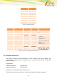
7 CEP Certified Accessories Product 12002 12003 12021 12016 12020 Description Power supply 230V AC / 12 V 6pin RJ11 connector DC Power cable 6pin RJ11 connector with open ends Magnetic Antenna / Pentaband FME female (Quad&UMTS) Rectangular Antenna / FME female Pentaband (Quad&UMTS) Patch Antenna/ Pentaband (Quad&UMTS) 12006 Roof-mount antenna* FME female waterproof, 900/1800 MHz 12004 RS232 cable 1.
8 Abbreviations Abbreviation Explanations CBM Cell Broadcast Message CBS Cell Broadcast Service CSD Circuit Switched Data DCE Data Circuit Terminating Equipment DTE Data Terminal Equipment DTMF Dual Tone Multi Frequency EFR Enhanced Full Rate EMC Electro-Magnetic Compatibility ETSI European Telecommunication Standards Institute FR Full Rate GPRS General Packet Radio Service GSM Global System for Mobile Communication HR Half Rate HSCSD High Speed Circuit Switched Data ITU-T ME
Abbreviation Explanations TE Terminal Equipment TS Telecom Services VSWR Voltage Standing Wave Ratio Table 9: Abbreviation 28
9 Mark of Conformity The CT63-E Terminal will carry the following certificates: 29
10 Service and Support To contact customer support please use the contact details below: Customer Support CEP AG Raiffeisenallee 12b 82041 Oberhaching Germany E-mail: support@cepag.de or Tel. +49-89-450 292 – 11 Information about CEP AG, products and accessories is available on the following web site: http://www.cepag.de. Please contact us via e-mail if you miss anything on the web and we will provide it to you personally via e-mail.
11 Documentation Change Log Revision Date Changes Rev 0.5 06.14.2013 First Official Release Rev 1.1 21.03.