
User manual

9
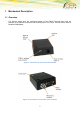
2 Electrical Description
The modem uses the following standard connectors:
RJ11 6-way (power connector)
Mini USB
SIM card reader
FME male coaxial jack (antenna connector)
Sub-D female socket, 9 pin (RS232 serial port)
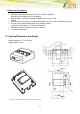
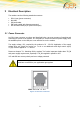
2.1 Power Connector
An RJ11 6-way connector, as shown and described below, serves as a means of supplying and
controlling DC power to the modem. It is necessary to connect an external power supply, since
the available power on the USB port is not sufficient to run the modem.
The supply voltage, VCC, required by the modem is 5V - 32V DC. Application of the supply
voltage does not switch the modem on. To do so an additional active-high control signal,
TO_IN, must be applied for > 1 second.
Please see chapter “3.1 Switching ON the modem” for further important details about TO_IN
and power supply requirements, especially if TO_IN is applied in parallel to VCC.
VCC and GND are reverse-polarity and over-voltage protected.
This does not apply for the GND on the antenna connector if this coax GND /
shield are connected to your applications group plane.
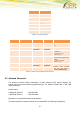
PIN: -> 6 5 4 3 2 1
Figure 4: RJ11 Pin Connector