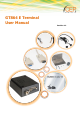
GT864 E Terminal User Manual Revision 1.
Important information This technical description contains important information for start up and use of the GT864 E Terminal. Read it carefully before you start working with the GT864 E Terminal. The warranty will be void should damage occur due to non-compliance with these instructions for use. We cannot accept any responsibility for consequential loss. We cannot be held responsible for material loss or personal injury that is due to incompetent use or non-compliance with the safety instructions.
not clearly states which electric data is valid for a component or a module, how to wire the device, which external components or additional devices can be connected or which parameters these components are allowed to have, a specialist must be contacted. Before putting a device into operation, it has to be clarified, whether this device or module is meant for the field of application. In case of doubt ask specialists or the manufacturer of the device.
Table of Contents Important information ......................................................................................................................... 2 Safety Instructions .............................................................................................................................. 2 1 2 Mechanical Description ................................................................................................................. 7 1.1 Overview ........................................
.2 How to install the modem..................................................................................................... 21 5.2.1 Power supply ................................................................................................................ 21 5.2.2 Securing the modem ..................................................................................................... 21 5.3 Antenna ...............................................................................................
Table Overview Table Table Table Table Table Table Table Table Table Table 1: Pin Description .................................................................................................................... 10 2: RJ11 Pin and Signals Description ........................................................................................... 10 3: Mini USB Signal Color ...........................................................................................................
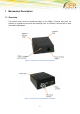
1 Mechanical Description 1.1 Overview The pictures below show the mechanical design of the GT864 E Terminal along with the positions of the different connectors and mounting holes. The GT864 E Terminal case is made of durable PC/ABS plastic.
Please note the following: Mounting holes positioned at two of the corners make it possible to securely bolt the modem into your application. Keypad, display, microphone, speaker and battery are not part of the modem. The SIM card is mounted in the modem, accessible by the user under a lid without any tools. The pins and electrical characteristics or the modem’s various connectors are described in “2. Electrical Description” Information about the antenna connector is found in “2.
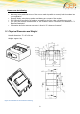
2 Electrical Description The modem uses the following industry standard connectors: RJ11 6-way (power connector) Mini USB (audio) SIM card reader FME male coaxial jack (antenna connector) Sub-D female socket, 9 pin (RS232 serial port) 2.1 Power Connector An RJ11 6-way connector, as shown and described below, serves as a means of supplying and controlling DC power to the modem. The supply voltage, VCC, required by the modem is in the range 5V - 32V DC.
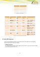
PIN Description 1 VCC 2 3 HR_IN 4 TO_IN 5 6 GND Table 1: Pin Description PIN Signal Direction Limits 1 VCC Input 5 – 32V 2 ADC_IN or not Input connected 0 – 32V 3 HR_IN Input 5 – 32V 4 TO_IN Input 5 – 32V 5 DIG_OUT / or Output not connected 5 – VCC max. 32V 6 GND - Input Description Positive power input, DC - No connection in GT864 E version - No connection in GT864 E version Positive edge triggered signal; used to switch on the modem VIH > 5V, VIL < 0.
2.2.1 GT864 E with Audio connector The USB connector supports the connectivity of a headset or any other audio equipment using the analogue microphone and loudspeaker interface of GT864-QUAD Terminal. The table below describes the signals on the USB connector.
Output Power: 2 Watt Peak (Class 4) GSM9001 Watt Peak (Class 1) GSM1800 Description of recommended antenna parameters: The antenna that the customer chooses to use should fulfil the following requirements: Gain Dual Band GSM 8501800MHz Depending by frequency band(s) provided by the network operator, the customer shall use the most suitable antenna for that/those band(s) 80 MHz in EGSM 900, 70 MHz if GSM 850, 170 MHz in DCS, 140 MHz PCS band > 1.
Signal Direction Limits Description 7 RTS Input > + 2,4V < 0.8 V Request to send 8 CTS Output > + 4V <-4V Clear to send 9 RI Output > + 4V <-4V Ring indicator Table 5: Electrical characteristics of the serial port signals 2.5.1 Serial Data The modem supports the standard data character format of Programmable baud rate Auto-configuration mode with auto-baud. 2.5.
Data Carrier Detect (DCD) DCD indicates that the DCE is receiving a valid carrier (data signal) when low. You can define the exact behaviour of DCD with an AT command. Ring Indicator (RI) RI indicates that a ringing signal is being received by the DCE when low. You can define the exact behaviour for RI with an AT command.
3 Operation 3.1 Switching ON the modem There are two ways to switch on the modem, once power is applied. assert TO_IN to high level for > 1s activate the RS232 control line DTR The modem is fully operational after 4 seconds. Logging onto a network may take longer than this and is outside the control of the modem. The modem can be configured to start up at the time power is applied by permanently tying power connector signals TO_IN (pin 4) and VCC (pin 1) together.
3.2 Switch OFF the modem The only way to power off the modem is to remove power. 3.3 Operating states / LED 3.3.1 Power up LED (green LED in the middle) The modem has a green power up LED, as depicted below, which is used to indicate various operating states. These states are described in following table.
4 Power consumption The following table shows you the power consumption of the GT864 E in different modes (average over 1 minute interval): [mA] @ 12V GT864 Standby < 20 GT864 idle mode <3 Table 7: Power consumption in idle and low power mode Safety and Product Care Please read the information in this section and the information in “Installation of the Modem”, before starting your integration work! 4.1 Safety instructions PLEASE READ THESE SAFETY INSTRUCTIONS AND KEEP A COPY OF THEM.
Never try to dismantle the modem yourself. There are no components inside the modem that can be serviced by the user. If you attempt to dismantle the modem, you may invalidate the warranty. The GT864 E Terminal must not be installed or located where the surface temperature of the plastic case may exceed 85°C.
disturbances it might cause. Protection is secured either by shielding the surrounding electronics or by moving the antenna away from the electronics and the external signals cable. The modem and antenna may be damaged if either come into contact with ground potentials other than the one in your application. Beware, ground potential are not always what they appear to be.
5 Installation of the modem This chapter gives you advice and helpful hints on how to integrate the GT864 E Terminal into your application from a hardware perspective. Please read the information given in “Safety and Product Care”, page 10 and then read the information in this section before starting your integration work. 5.1 Where to install the modem There are several conditions which need to be taken into consideration when designing your application as they might affect the modem and its function.
5.1.4 Network and Subscription Before your application is used, you must ensure that your chosen network provides the necessary telecommunication services. Contact your service provider to obtain the necessary information. If you intend to use SMS in the application, ensure this is included in your (voice) subscription. Consider the choice of the supplementary services 5.2 How to install the modem 5.2.1 Power supply Use a high-quality power supply cable with low resistance.
connectors, antenna placement, and the surrounding area. You should also determine whether the antenna needs to be grounded or not. Your local antenna manufacturer might be able to design a special antenna suitable for the application. 5.3.2 Antenna type Make sure that you choose the right type of antenna for the modem.
Path-loss occurs as the strength of the received signal steadily decreases in proportion to the distance from the transmitter. Shadowing is a form of environmental attenuation of radio signals caused by hills, buildings, trees or even vehicles. This can be a particular problem inside buildings, especially if the walls are thick and reinforced. Multi-path fading is a sudden decrease or increase in the signal strength.
6 Technical Data Product features: Dual-band EGSM 900/1800/MHz GSM 900 Power class 4 (2W) GSM 1800Power class 1 (1W) Control via AT commands according to GSM 07.05, 07.07 and proprietary Telit Serial Port Multiplexer GSM 7.10 SIM Access Profile Supply voltage range: 5 – 32 V/DC TCP/IP stack access via AT commands Sensitivity: o -107 dBm (typ) @ 900 MHz o -106 dBm (typ.)@ 1800 Overall dimensions (excluding connectors): 77 x 67 x 26mm Weight: ca.
Asynchronous transparent circuit switched Data (CSD) up to 14,4 kbps Asynchronous non-transparent circuit switched Data (CSD) up to 9,6 kbps V.
7 Abbreviation Abbreviation Explanations CBM Cell Broadcast Message CBS Cell Broadcast Service CSD Circuit Switched Data DCE Data Circuit Terminating Equipment DTE Data Terminal Equipment DTMF Dual Tone Multi Frequency EFR Enhanced Full Rate EMC Electro-Magnetic Compatibility ETSI FR European Institute Full Rate GPRS General Packet Radio Service GSM Global System for Mobile Communication HR Half Rate HSCSD High Speed Circuit Switched Data ITU-T ME International Telecommunicatio
8 Mark of Conformity 27
9 Service and Support To contact customer support please use the contact details below: Customer Support CEP AG Raiffeisenallee 12b 82041 Oberhaching Germany E-mail: support@cepag.de or Tel. +49-89-450 292 – 11 Information about CEP AG, products and accessories is available on the following web site: http://www.cepag.de. Please contact us via e-mail if you miss anything on the web and we will provide it to you personally via e-mail.
10 Documentation Change Log Revision Date Changes Rec. 1.0 16.06.2013 Initial Release Rec 1.2 21.03.