
User manual


10
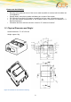
PIN
Description
1
VCC
2
3
HR_IN
4
TO_IN
5
6
GND
Table 1: Pin Description
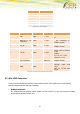
PIN
Signal
Direction
Limits
Description
1
VCC
Input
5 – 32V
Positive power input,
DC
2
ADC_IN or not
connected
Input
0 – 32V
-
- No connection in
GT864 E version
3
HR_IN
Input
5 – 32V
- No connection in
GT864 E version
4
TO_IN
Input
5 – 32V
Positive edge triggered
signal; used to switch
on the
modem
VIH > 5V, VIL < 0.5V
Power on: t > 1s
5
DIG_OUT / or
not connected
Output
5 – VCC
max. 32V
- No connection in
GT864 E version
6
GND
Input
-
Negative power
(ground) input and
return
path for TO_IN and
HR_IN
Table 2: RJ11 Pin and Signals Description
2.2 Mini USB Connector
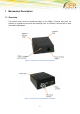
There exist several different variants of the terminal module, all in (almost) the same housing,
and all equipped with the USB-type connector:
GT864 E with Audio
The GT864 ETerminal provides "audio signals" on that connector, so you can connect a handset
or microphone/speaker system here.