STD32 User Manual Revision 2.
Important information This user manual contains important information to start up and use the STD32 device. Read it carefully before you start working with the STD32. The warranty will be void should damage occur to the device due to non-compliance with these instructions. We cannot accept any responsibility for any loss resulting from this non-compliant use. We cannot be held responsible for material loss or personal injury that is due to incompetent use or non-compliance with the safety instructions.
Before putting the device into operation it should be checked that there is no current leakage on the housing. In case measurements need to be performed with an opened housing, an isolating-transformer has to be integrated for safety reasons. Alternatively the voltage can be supplied by an appropriate power supply which complies with the safety regulations. All wiring work has to be done in a voltage free state only.
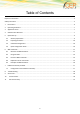
Table of Contents Important information ...................................................................................................................................................... 2 Safety Instructions ............................................................................................................................................................ 2 1 Introduction ............................................................................................................................
Overview of Tables Table 1: Allocation of screw terminals .............................................................................................................................. 8 Table 2: Configuration Commands ................................................................................................................................. 11 Table 3: Inputs & Outputs commands ............................................................................................................................
1 Introduction Thank you very much for purchasing our CEP STD32 telemetry device! The STD32 enables the user to remotely switch ON or OFF electronic devices and to receive alarm messages via SMS. You can switch devices either with an SMS or using a simple voice call. Alarm messages (SMS) can be received with any mobile phone supporting SMS functionality. With the STD32 you can also receive alarm messages by E-Mail.
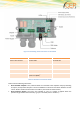
2 Operating Conditions Operate the STD32 only with a supply voltage between 7-32V DC and have in mind the polarity! (see picture1) Use a stabilized power supply with minimum 1A output current. (We recommend using only the original CEP power supply). If you use a mains adapter for power supply it has to conform to the VDE regulations.
Figure 1: Positioning of the connectors on the STD32 Outputs Inputs Power Supply Screw 1: RLY1 Contact 1 Screw 4: DIN1 Screw 8: VIN Screw 2: RLY1 Contact 2 Screw 5: DIN2 Screw 9: GND Screw 3: RLY2 Contact 1 Screw 6: Not used Screw 4: RLY2 Contact 2 Screw 7: Common ground for inputs 1 & 2 (GND) Table 1: Allocation of screw terminals Please note the following instructions: Screw terminal “Outputs”: Here, electrical loads are connected to the respective relay.
Technical data”). Screw terminal “Power Supply”: Power supply is applied on screw 8 (VIN +) and screw 9 (GND). The used terminal blocks are designed for cables with a cross-section of 0.08mm² to 1,3mm² (both single core and multistring). The (FME-Female) connector “Antenna” is used to connect the GSM antenna. Please observe the maximum output voltage of the relays and the maximum input voltage of the inputs! (Refer to Section 2 Operating Conditions).
The “incognito” or “private call” function of the mobile must be deactivated in order to be able to administer the STD32. In other words, the Master Mobile has to transmit the mobile phone number with every call. Please refer to the user guide of your mobile telephone to change this setting. To test the setting you can call a different mobile phone; there your phone number or name should be displayed. 5.
6 SMS Commands There is a wide range of special commands which can be used to configure the device, request information or to trigger certain actions. All the commands are designed to be easy to enter even when using a standard phone. This chapter describes all the commands the device will understand and how to use them. The format of the SMS commands is explained in Section 6.3. 6.
Inputs & Outputs commands I2:xxx debounce time for input 2 (in seconds) V1:x 1 - invert input 1 0 - normal input 1 V2:x 1 - invert input 2 0 - normal input 2 Table 3: Inputs & Outputs commands CLIP commands CL: add clip list number, asterisk symbol (*) is also supported CD: remove clip list number Table 4: CLIP commands DATA commands EMAIL: 1 - enable E-Mail feature 0 - disable E-Mail feature default is enabled SMTPIP:XXXXX defines SMTP server IPv4 address example SMTPIP:"smtp.aol.
DATA commands FROM: SSL: TO: SUBx: BODY: TESTMAIL max length is 64 (according to RFC0821, chapter 4.5.3. SIZES) default is empty defines E-Mail sender example FROM:"p.szymczak@cetec.cc" max length is 25 default is empty Send SSL encrypted E-Mails: Activate SSL: SSL:1 Deactivate SSL: SSL:0 defines up to 5 E-Mail recipients (separated by ";"), each one max 25 characters example TO:"support@cepag.
6.2 Using Variables You can use text strings “variables” in order to display more information in event texts. When a variable is included in an event text string, the variable is replaced by the value it is intended to represent in the string that is sent to the user, either vian SMS or E-Mail.
All commands (except R: and ST?) must end with a full stop “.”! All commands can be sent in one SMS; each command has to be separated from the next by a full stop (see examples). If you need a full stop "." in a parameter as it is for example in an E-Mail address or in some APNsettings, the complete parameter has to be put into inverted commas (“...”) (e.g. "h.muster@aol.com"), as otherwise the "." would be seen as the end of the command. Parameters for representing seconds (e.g. command “O1:xxxxx.
Please note that the brackets “<“ and “>“in the following commands are not part of the commands but are included in order to increase the readability of the overview! Four additional alarm numbers (mobile phones) can be defined using C2: - C5: commands. These numbers are allowed to set relay 1 by a call and they are informed vian SMS in case of Start-up or events. These numbers are not allowed to send configuration SMS messages unless they include the password in the SMS.
Removing the clip from the extended clip list 9851 CD:+491721234567. Table 9: Examples of SMS Commands 7 E-Mail functionality via GPRS Netzbetreiber z.B Vodafone Internet SMTP E-Mail Server z.B. AOL IP Port Benutzername Passwort APN Benutzername Passwort STD32 Figure 2: E-Mail functionality via GPRS The STD32 enables you to get messages not only via SMS but also via E-Mail.
In most cases it is not necessary to configure any of the SMTP settings as the device come preconfigured for the e-mail server subscribed by CEP, which is a free service for STD32 users.
10 Technical data GSM: Quad Band EGSM 850/900/1800/1900 MHz Compatible with ETSI GSM Phase 2+ Standard Output power: Class 4 (2W @ 850/900 MHz) Class 1 (1W @ 1800/1900 MHz) Temperature range: -30°C - +75°C Weight approx. 220 grams Dimensions: 150x65x45 mm (l x w x h) Supply voltage: 7-32V Current consumption during normal operation: ~14 mA, peak up to 1A Max. output current Output 1&2: 5A Max. output voltage Output 1&2: 30V DC; 250V AC Max.
11 Document history Revision Datum Changes Rev. 1.0 16th Dec 2010 Original file Rev.1.1 14th Jan 2011 Update Rev 1.2 23rd Jan 2011 Added Configuration Tool Rev 1.3 6th June 2011 Minor Corrections Rev 1.4 9th June 2011 Corrected relay voltage mistake Rev 1.5 10th December 2013 Change from Telic to CEP, Complete Update Rev. 2.0 31st March 2015 Content adapted to new hardware Rev. 2.1 11th June 2015 Update Status LEDs, E-Mail Commandos, Section 4, 6.2, 7.