
User manual


8
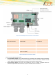
Figure 1: Positioning of the connectors on the STD32
Outputs
Inputs
Power Supply
Screw 1: RLY1 Contact
1
Screw 4: DIN1
Screw 8: VIN
Screw 2: RLY1 Contact
2
Screw 5: DIN2
Screw 9: GND
Screw 3: RLY2 Contact
1
Screw 6: Not used
Screw 4: RLY2 Contact
2
Screw 7: Common ground for
inputs 1 & 2 (GND)
Table 1: Allocation of screw terminals
Please note the following instructions:
Screw terminal “Outputs”: Here, electrical loads are connected to the respective relay. By activating
an output, the respective rekay RLY 1 or RLY 2 establishes an electrical connection between contact
1 and 2. Please consider the limit values for all RLY’s (see article 10 Technical data).
Screw terminal “Inputs”: The inputs are activated as soon as a voltage is applied within the
specified range between the terminals (e.g. Input 1 and GND; refer to Section 0, ”