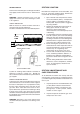
Natural Gas MODEL: L.P.G. MB055PEH MB055 MB105 MB155 MB185 MB265 MB405 WARNING: If the information in these instructions are not followed exactly, a fire or explosion may result causing property damage, personal injury or death. - Do not store or use gasoline or other flammable vapours and liquids in the vicinity of this or any other appliance. - WHAT TO DO IF YOU SMELL GAS - Gas Emergency Services 0800 111 999 • Do not try to light any appliance.
Contents 2 PART ONE - OWNER'S OPERATING INSTRUCTIONS 2 2 SECTION 1 / START-UP PROCEDURES Before Start-Up 3 Operating Instruction & Shut-Off Procedures 4 After Start-Up 4 SECTION 2 / CAUTION 4 5 5 5 SECTION 3 / MAINTENANCE & CARE PROCEDURE Pool & Spa Water Chemistry Cold Weather Operation Winterizing the Pool & Spa Heater 6 PART TWO - INSTALLATION/SERVICE INSTRUCTIONS 6 SECTION 1 / RECEIVING EQUIPMENT 6 SECTION 2 / GENERAL SPECIFICATIONS 8 11 11 14 15 16 16 20 SECTION 3 / INSTALLATION INS
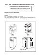
PART ONE - OWNER'S OPERATING INSTRUCTIONS FOR YOUR SAFETY - READ BEFORE OPERATING WARNING: IF YOU DO NOT FOLLOW THESE INSTRUCTIONS EXACTLY, A FIRE OR EXPLOSION MAY RESULT, CAUSING PROPERTY DAMAGE, PERSONAL INJURY OR LOSS OF LIFE. SECTION 1 / START-UP PROCEDURES BEFORE START-UP BURNERS Clean air louvres of dust, lint and debris. Keep heater area clear and free from combustibles, flammable liquids and chemicals. Do not obstruct the flow of combustion and ventilating air.
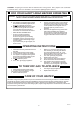
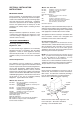
CAUTION: Propane gas is heavier than air and will settle on the ground. Since propane can accumulate in confined areas, extra care should be exercised when lighting propane heaters. FOR YOUR SAFETY READ BEFORE OPERATING WARNING: IF YOU DO NOT FOLLOW THESE INSTRUCTIONS EXACTLY, A FIRE OR EXPLOSION MAY RESULT CAUSING PROPERTY DAMAGE, PERSONAL INJURY OR LOSS OF LIFE. C. A. This appliance is equipped with an ignition device which automatically lights the pilot. Do not try to light the pilot by hand. B.
AFTER START-UP SECTION 2/CAUTION Feel the inlet and outlet pipes. Outlet pipe should be only slightly warmer than the inlet. It should not be hot. Elevated water temperature can be hazardous, and the U. S. Consumer Product Safety Commission recommends the following guidelines: WARNING: Should overheating occur or the gas supply fail to shut off, turn off the manual gas control to the appliance. 1. Spa or hot tub water temperatures should never exceed 40°C (104°F).
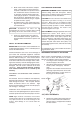
3. Make visual check of the burner and pilot flame. Flame pattern on the main burner and pilot is indicated in the previous illustration. Yellow flame means restriction of the air openings. Lifting or blowing flame indicates high gas pressure. Low flame means low gas pressure. Should this occur, shut the heater off and contact your gas supplier or qualified service agency. 4. On indoor heaters, clean room intake openings to assure adequate flow of combustion and ventilation air.
PART TWO - INSTALLATION/SERVICE INSTRUCTION SECTION 1 / RECEIVING EQUIPMENT WARNING: This appliance must be installed and serviced by a Gas Safe registered installer. On receipt of your equipment it is suggested that you visually check for external damage to the carton. If the carton is damaged, a note should be made on the delivery note when signing for equipment. Remove the heater from the carton and if it is damaged, report the damage to the carrier immediately. Save the carton.
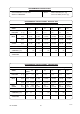
PERFORMANCE SPECIFICATIONS II2H3P GAS CATEGORY, TYPE, AND SUPPLY PRESSURE. G20 @ 20 mbar (8 in. wg) G31 @ 37 mbar (14.8 in. wg) PERFORMANCE SPECIFICATIONS - NATURAL GAS GAS TYPE AND SUPPLY PRESSURE MODEL G20 @ 20 mbar (8 in. wg) 055 105 155 185 265 405 6.3 ( 2.5 ) 6.8 ( 2.7 ) 7.7 ( 3.1 ) 8.1 (3.2) 8.3 (3.3) 8.7 (3.5) GROSS kW (Btu/h) 12.9 (44,000) 26.67 (91,000) 38.98 (133,000) 49.53 (169,000) 71.5 (244,000) 108.4 (370,000) NET kW (Btu/h) 11.6 (39,600) 24.0 (81,900) 35.
Models 185, 265 & 405 SECTION 3 / INSTALLATION INSTRUCTIONS BS. 6891; BS. 6644; Installation of low pressure pipework. Installation of Gas Fired Hot Water Boilers 60kW to 2MW. CP 341; Water Supply. British Gas Publications: IM2; Purging Procedures on Non-domestic Gas Installations. IM5; Soundness Testing Procedures for Industrial and Commercial Gas Installations. IM11; Flues for Commercial and Industrial Gas Fired Boilers and Air Heaters. Model Water Byelaws.
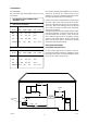
CLEARANCES ALL HEATERS For clearances from combustible surfaces, see the chart below. For servicing, provide at least 600mm (24") in front of the heater for burner tray removal, and at least 450mm (18") on water connection side of the heater to inspect and delime the heat exchanger. CLEARANCE FROM COMBUSTIBLE MATERIAL (mm) Heaters must not be installed under an overhang of less than 1.0m (3 feet) from the top of the heater. Three (3) sides must be open in the area under the overhang.
OUTDOOR HEATERS 105 & 155 Models FLUE TERMINAL (Outdoor) Stackless Top Illustration These heaters are certified by British Gas plc for outdoor installation, when equipped with the approved tops designated for outdoor use. Top Vent Opening WARNING: The heater shall not be located in an area where water sprinklers, or other devices, may cause water to spray through the cabinet louvres and into the heater.
INDOOR HEATER 185, 265 & 405 Models FLUE TERMINAL (Indoor) Draught Diverter Illustration The design is also certified by British Gas plc for indoor installation when fitted with the appropriate draught diverter and a suitable flue system to outside. Note that the heater must be in a room separated from living rooms and provided with appropriate ventilation direct to the outside. 1. Remove the louvred jacket top by removing four (4) No.10 flat head screws. 2.
SPECIFICATIONS & DIMENSIONS 055 - 105 - 155 MODEL FLUE DIA WATER CONNECTIONS 055 105 155 mm (in.) 100 (4) 127 (5) 152 (6) 1-1/2" NPT 1- 1/2" NPT 2" NPT DIMENSIONS - 055 SHIPPING WEIGHT kg (lbs) APPLIANCE DIVERTER 31.8 (70) 2.3 (5) 48 (105) 3.5 (8) 62 (135) 3.5 (8) Model Only 130mm (5 -1/8") 60mm (2 - 3/8") 825mm (32 - 1/2") 620mm (24 - 1/2") 525mm (20 - 3/4") 455mm (18") Gas Connection 65mm (2 - 1/2") 325mm (12 - 7/8") DIMENSIONS - 105 dim055.
DIMENSIONS - 155 Model Only 220mm (8 - 3/4") 85mm (3 - 3/8") 900mm (35 - 1/2") 1140mm (44 - 7/8") 770mm (30 - 3/8") 680mm (26 - 3/4") Gas Connection 370mm (14 - 1/2") 390mm (15 - 3/8") 610mm (24") SPECIFICATIONS & DIMENSIONS 185 - 265 - 405 MODEL 185 265 405 WIDTH (A) mm (in.) 464 (18 1/4) 568 (22 3/8) 743 (29 1/4) FLUE DIA WATER CONNECTIONS mm (in.) 150 (6) 175 (7) 230 (9) 2" NPT 2" NPT 2" NPT SHIPPING WEIGHT kg (lbs) APPLIANCE DIVERTER 86.8 (191) 5.
VENTILATION REQUIREMENTS The flue/chimney design should avoid the formation of excessive quantities of condensate and for this reason it is recommended that all chimneys are suitably insulated and lined. The heater must have both ventilation and combustion air. Safe and efficient operation of the heater is vitally dependant upon a good supply of fresh air to the room in which the appliance is installed.
Honeywell Gas Valve GAS SUPPLY CONNECTIONS Burner Pressure Adjustment Gas piping must have a manual shut-off valve located outside the heater jacket. All gas piping should be tested after installation in accordance with local codes. CAUTION: The heater and its manual shut off valve must be disconnected from the gas supply during any pressure testing of that system at test pressures in excess of 150mbar (2.2psi).
PLUMBING FOR WATER CONNECTIONS LEFT SIDE WATER CONNECTION CONVERSION Figure 2 Front Screws Rain Shield Front Panel 185, 265 & 405 Models Only fig2.tif Dis-assembly: 1. Remove the jacket top, upper side panels, right and left side access panel (see figure 1). 2. Remove rain shield front and side panel assembly as follows: (see figure 2). a) Remove front screws attaching rain shield to the vertical surface behind the control compartment.
7. a) Disconnect the three (3) pin sensor plug from the poolstat circuit board (see figure 5). b) Push the connector plug and wires down through the control box holes (see figure 5) and then through the inner jacket panel hole into the heat exchange area (see figure 4). 14. OPTIONAL, re-route the AGS wires to the left side and overheat thermostat capillary to the right side. Connect the wires to the sensors in the header castings. 15. Replace the flue collector.
CONNECTIONS 2" CPVC Adapters All Models LOCATION The heater requires water flow and pressure to operate properly. It must therefore be installed downstream of the discharge side of the filter pump. A typical installation is plumbed as follows: 1. The inlet side of the filter is plumbed to the discharge side of the filter pump. mbsmall.tif 2. The outlet side of the filter is then plumbed to the inlet of the heater. 3. The outlet of the heater is plumbed to the return line to the pool or spa.
055 Models Only 1 2 IN OUT gasket.tif S80 UNITHERM GOVERNOR OPERATION Does not apply to 105 Model 055hdr.tif The patented Unitherm Governor is a thermostatic mixing valve specifically designed to maintain constant heater internal temperature between 40.6 to 46.1°C despite continually changing flow rates from the filter and changing pool temperatures. This narrow range is needed to prevent damaging condensation on the burners which will occur if the heater runs for any length of time below 37.8°C.
EXTERNAL AUXILIARY BYPASS VALVE (Where Required) An auxiliary bypass valve should be used when flow rates exceed those shown in the table in the 'Connections' section on p18. (usually a high performance pump size larger than two HP will exceed this flow rate). This valve is required to complement the function of the automatic bypass valve, particularly when starting the heater in winter or early spring when the spa or pool temperature is down below 10°C.
WIRING DIAGRAM 055-105-155 MODELS ONLY IGNITION DEVICE-ROBERTSHAW versa_wiring_08.01.
WIRING DIAGRAM 185-265-405 MODELS ONLY IGNITION DEVICE-ROBERTSHAW Rpwiring.
SECTION 4 / SERVICING INSTRUCTIONS GENERAL LOCATION OF CONTROLS 055 MODEL Manual High Limit Reset Button 105 MODEL Pressure Switch Burners & Pilot Drain Valve Unitherm Governor (Bronze Units Only) Gas Valve Bypass Valve High Limits & Overheat Thermostats Solid State Thermostat & Ignition Control 105cont.tif High Limits & Overheat Thermostats 155 MODEL Solid State Thermostat Control Unitherm Governor Ignition Control Pressure Switch Drain Valve Gas Valve Thermal Fuse 8110.
GENERAL LOCATION OF CONTROLS - continued. 185-265-405 MODEL Overheat Thermostat Capillary (Located in Return Header) Bypass Drain Plug (Located in Return Header) Ignition Control (IID) AGS Hi-Limit (Located in Inlet/Outlet Header) Solid State Thermostat Module Unitherm Governor Ranco LM7 Overheat Thermostat Drain Valve Pressure Switch Transformer Roll-Out Safety Switch Gas Valve Pilot rpunit.tif 155 Model 185,265 & 405 Models CONTROL PANEL REMOVAL CONTROL PANEL REMOVAL 1. Remove lower door. 2.
185,265 & 405 Models 185,265 & 405 Models OFF POOL On/Off Switch SPA Service Pressure/High Limit Thermostat Knob & Knobstop Ring Call forHeat Power ELECTRONIC rpcont.tif There are four operational indicator lamps located on the 185, 265 & 405 Spa/Pool control panel. They are as follows: 405view.tif 1. The “Power” (green) lamp is on when power is applied to the RP 2100 Spa/Pool heater. Green ON – Power to Heater Normal All Models TEMPERATURE CONTROLS 2.
All Models FLAME ROLL-OUT SAFETY SWITCH PRESSURE SWITCH ADJUSTMENT 1. With pump and heater on, turn adjustment knob (clockwise) until a click is heard from the gas valve. 2. Turn adjustment knob (counter clockwise) 1/4 turn. 3. Turn pump off and on several times. Heater should shut off immediately. If it does not,repeat steps above until proper adjustments is made. rollout.
055, 105 & 155 Models 3. To remove the manual reset high limit, follow the procedure for the high limit thermostat but in addition, disconnect the electrical connections and release its mounting bracket from the side panel by removing the M4 nut at the front of the bracket. The thermostat can then be removed from its bracket. Ensure thermostat phial is correctly located in its pocket. 4. Reverse above procedure to reinstall. GAS VALVE REMOVAL 1. Remove burner tray. (See burner drawer removal procedure).
185, 265 & 405 Models All Models PILOT REMOVAL AND CLEANING CONTROL IMMERSION WELL REPLACEMENT 1. Disconnect pilot tubing, and wires from gas valve. 2. Remove pilot assembly from burner tray. 3. Remove pilot from bracket. 4. Remove pilot injector and clean with wire or small brush. CAUTION! Do not enlarge hole in pilot orifice. 5. Reverse above procedure to re-install. 1. Shut water off to heater and drain heat exchanger. 2. Remove jacket top panel. 3.
All Models To test the operation of the Unitherm Governor, place in hot water (over 43°C) and watch for movement against spring. If there is no movement, replace unit. DESOOTING PROCEDURE CAUTION: SOOT IS COMBUSTIBLE. EXERCISE EXTREME CARE. NEVER USE A WIRE BRUSH. 055, 105 & 155 Models COMBUSTION CHAMBER REMOVAL Soot can clog areas between fins and cause eventual tube failure. Any sign of soot at the base of the burners or around the outer jacket indicates a need for cleaning. 1.
SECTION 5 / TROUBLE SHOOTING GUIDE IMPORTANT NOTICE: These instructions are primarily intended for the use of qualified personnel specifically trained and experienced in the installation of this type of heating equipment and related system components. Installation and service personnel must be Gas Safe Registered. Persons not qualified shall not attempt to install this equipment nor attempt repairs according to these instructions.
PROBLEM CAUSE SOLUTION Pilot outage. Low gas pressure..................... Adjust gas pressure. Restricted pilot......................... Clean pilot. Weak pilot generator.................. Replace pilot. Faulty Detection Electrode or PCB Yellow lazy flame Low gas pressure...................... Adjust gas pressure. *Insects or debris clogging burner intake ports.....................Clean burners.
055, 105 & 155 Models WARNING HIGH VOLTAGE For qualified Technicians ONLY ELECTRICAL (ELECTRONIC IGNITION IID) *NOTE: This heater is equipped with an ignition module that shuts off pilot gas if pilot fails to light after the third attempt. This is identified by the green LED flashing on the ignition module. To reset, interrupt power to heater.
ELECTRICAL (SOLID STATE THERMOSTAT IID) 055, 105 & 155 Models If the pool/spa water is too cold, troubleshoot the system as follows: Check voltage at 24 V terminals. VOLTAGE BETWEEN 21.5-28.5 V. Set control to max. temperature. After 2-3 cycles, check water temperature. VOLTAGE OUTSIDE RANGE 21.5-28.5 V. Check transformer, 23•20 V supply, correct as necessary.If 230 V side of transformer is open circuit, check combustion chamber for heat leaks Check 3 Amp fuse.
185, 265 & 405 Models - IID DIAGNOSTIC FLOW CHART HEATER WILL NOT FIRE • Check for 230 V Power to Transformer (Circuit Breaker,Time Clock, Wire Connections) • Check for Fireman Switch/Remote Thermostat Operation (Red Jumper Wire from TP4 to TP5) Bypass If Necessary. • Check for 24 VAC from TP6 to TP7 (Transformer Output) If No Power, Replace Transformer. • Check Combustion chamber for heat leaks START "Green" Power Light "ON" NO Temporary Condition may have caused problem.
From Pg 34 • Check for 24 VAC Power to IID - (24 V to 24V GND Terminals on IID). If No Power, Replace heater Control Board, or wire harness to IID. • Check for Spark at IID Spark Terminal (Remove Hi-Tension Lead from IID ModulePosition end near spark terminal. Turn control on. If spark jumps to wire, check Hi-Tension wire, insulators, ceramic ignitor and gap. If no spark jumps to wire, replace IID Module.
SECTION 6 REPLACEMENT PARTS LIST 055 Model NOTE: To supply the correct part it is important that you state the model number, serial number and type of gas when applicable. spares2.pcx Pilot ( Silver ) Pilot ( Black ) europilot.tif 1-P 2-P 5-P 6-P 2-G 4-P 3-P inject.tif 8-P 7-P softlite.
Key Description - 055 Model Part Code B 1-B BURNER TRAY Burner Tray w/Gas Valve Natural Burner Tray w/Gas Valve Propane Burner Burner Injector Natural No.50 Burner Injector Propane No.
REPLACEMENT PARTS LIST 105 Model 1-V 2-V 1-S 6-C 16-H 2-G 2-C 2-S softlite.tif 2-H 6-H 11-H 3-C 8-H 7-H 14-H 12-H 4-H 1-H 6-S 3-H 5-C 2-M 1-R 9-M 4-J 5-M 10-M 4-S 1-M 4-M 6-S 3-M Pilot (Silver) inject.tif 1-B 3-S 1-P spares105_2.tif 2-P 1-G 4-P 3-P 2-B 2-G Pilot (Black) 3-J 3-B 5-S 5-P 4-C 6-P 2-J 8-P 10-12-01 38 europilot.
Key Description - 105 Model Part Code B 1-B BURNER TRAY Burner Tray w/Gas Valve Natural Burner Tray w/Gas Valve Propane Burner Burner Orifice Natural No.50 Burner Orifice Propane No.59 301210 350079 350350 2-B 3-B C CONTROLS 2-C 3-C 4-C 5-C 6-C Automatic Reset Thermostat High Limit Manual Reset 102ºC Thermostat Control (Solid State) Potentiometer Temperature Sensor 601549 M3029 600960 600961 600962 G 1-G 2-G GAS VALVE Honeywell Gas Valve L.P.G.
REPLACEMENT PARTS LIST 155 Model 12-H 2-C bits.tif Pilot (Silver) Pilot (Black) inject.tif europilot.tif 1-P 2-P 5-P 6-P 2-G 4-P 3-P 8-P 7-P softlite.
Key Description - 155 Model Part Code B 1-B BURNER TRAY Burner Tray w/Gas Valve Natural Burner Tray w/Gas Valve Propane Burner Burner Orifice Natural No.49 Burner Orifice Propane No.57 301210 350078 350083 C 1-C 2-C 3-C 5-C 6-C 7-C CONTROLS Thermostat Pocket, High Limit High Limit 60ºC (140ºF) High Limit Manual Reset 102ºC Thermostat Control (Solid State) Potentiometer Temperature Sensor M3028 600893B M3029 600960 600961 600962 G 1-G 2-G GAS VALVE Honeywell Gas Valve L.P.G.
REPLACEMENT PARTS LIST 185, 265 & 405 Model 3-V 17-H 16-H 1-V 1-C 5-C 2-S 15-H 13-H 11-H 14-H 14-M 7-H 10-H 9-H 12-H 2-H 6-H 2-C 8-H 7-S 4-H 3-H 18-H 10-S 8-S 2-M 4-S 5-S 12-S 1-M 4-M 3-C 3-M 13-M 11-M 18-H 4-J 1-B 4-S 6-S 5-M 1-J 3-B 2-J 4-B 6-C 1-G 3-S Pilot (Silver) Pilot (Black) europilot.tif inject.tif 1-P 5-P 6-P 2-P 2-G 4-P 3-P 7-P softlite.
Key Description - 185, 265 & 405 Models B 1-B BURNER TRAY Burner Tray w/Burners Burner Tray w/o Burners Burner Tray w/Gas Valve Natural Burner Tray w/Gas Valve Propane Burner Burner Orifice Natural No.50 Burner Orifice Propane No.59 265 405 301210 350079 350350 301210 350079 350350 SPMB405 SPMB403 301210 350079 350350 C 1-C 2-C 3-C 5-C 6-C CONTROLS Thermostat Pocket, High Limit High Limit 60ºC (140ºF) P.
185, 265 & 405 Replacement Parts List (continued) Key Description P 1-P 2-P PILOT (Silver) Pilot Natural/Propane Pilot Orifice Natural Pilot Orifice Propane Pilot Tube Hi-Tension Wire 265 405 600799 M3274 601218 400607 650998 600799 M3274 601218 400607 650998 600799 M3274 601218 400607 650998 7-P 8-P PILOT (Black) Pilot Natural/Propane Pilot Orifice Natural Pilot Orifice Propane Pilot Tube Hi-Tension Wire M3685 M3687 M3688 M3690 M3696 M3685 M3687 M3688 M3690 M3696 M3685 M3687 M3688 M3690 M3696
Booklet issue 12 27-08-03 Station Lane Industrial Estate Witney Oxon. Tel. 01993 778855 Fax.