
User's Manual


User Manual
©2007 Cervis, Inc.
3
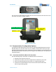
Figure 3. Female Twelve (12) Pin Connector
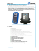
The unit has five status/diagnostic LEDs that are used to determine the state of the unit.
The LEDs are shown in Figure 4 below.
Figure 4. BU-902F LEDs
1.4 Communication Configuration Options
A standard SmaRT 902 System comes with one PTO-902 Handheld Remote and one
BU-902F Base Unit, but each base unit can establish communication with up to eight
PTO-902 Handheld Remotes. Each handheld must first establish a communications link
with the base unit before the base unit can recognize the handheld unit. This process is
called Association.
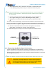
1.4.1 Associate Handheld to Base Unit Procedure
Use the following step to Associate a handheld remote to a base unit.
1. Remove power from the base unit.
2. Stand near the base unit in line of sight with the handheld in your hand.
3. Press and hold both buttons (see Figure 5). TX lights steady green.
4. Continue to hold both buttons for the five seconds it takes for the LINK
LED to begin flashing yellow.
TX/RX
–
Yellow when
transceivin
g
POWER OK
–
Yellow
Health OK
–
Green pulse/sec