™ ™ BU-9H16AF-8F-8V-RS Base Unit User Manual DN: U064.1-SmaRT_BU-9H16AF-8F-8V-RS 2011 Cervis, Inc.
SmaRT BU-9H16AF-8F-8V-RS This document is the property of Cervis, Inc. and cannot be copied, modified, e-mailed, or reproduced without the express prior written consent of Cervis, Inc. Cervis, Inc. reserves the right to change this manual or edit, delete, or modify any information without prior notification. FCC Statements 15.19 – Two Part Warning This device complies with Part 15 of the FCC rules.
900MHz Base Unit Manual Table of Contents List of Figures ............................................................................................................................... i Related Documents ...................................................................................................................... ii Cervis Inc. Safety Precautions ................................................................................................... 1 1.0 BU-9H16AF-8F-8V-RS Base Unit .................
SmaRT BU-9H16AF-8F-8V-RS Definitions/Notes Associate/Association Mode where by SmaRT handhelds and base units are paired for operation (ID’s exchanged). This mode is used to commission spare handhelds or base units. DSSS Direct Sequence Spread Spectrum; an advance wireless communication technology. Disassociation The process of up-pairing a handheld from a base units ID memory. PTO Push-to-Operate: Command broadcast only while a button is depressed. The command ends when the button is released.
900MHz Base Unit Manual Cervis Inc. Safety Precautions Read and follow all instructions. Failure to abide by Safety Precautions may result in equipment failure, loss of authority to operate the equipment, and personal injury. Use and maintain proper wiring. Follow equipment manufacturer instructions. Improper, loose, and frayed wiring can cause system failure, equipment damage, and intermittent operation.
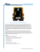
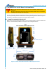
SmaRT BU-9H16AF-8F-8V-RS 1.0 BU-9H16AF-8F-8V-RS Base Unit Figure 1. SmaRT BU-9H16AF-8F-8V-RS-INT Base Unit The SmaRT™ BU-9H16AF-8F-8V-RS features sixteen FET, high side switching outputs or switch-to-ground digital inputs. The versatile, programmable digital inputs/outputs can be customized by Cervis to fit specific user applications. The BU-9H16AF-8F-8V-RS accepts a broad range of input power with operating voltages ranging from +10VDC to +30VDC.
900MHz Base Unit Manual 2.0 SmaRT BU-9H16AF-8F-8V-RS in SmaRT Remote Control Systems The basic standard SmaRT Remote Control System consists of at least one SmaRT base unit, a SmaRT remote control unit, and the wiring harness that is used to connect the base unit to the controlled apparatus. A single base unit is capable of communicating with multiple SmaRT remotes.
SmaRT BU-9H16AF-8F-8V-RS 2.1 BU-9H16AF-8F-8V-RS Base Unit Installation Make sure the machine to which the base unit is to be installed is disabled during installation. Base Units subjected to the elements must be vertically installed. Cervis recommends installing all base unit top-side UP (vertical) Use the configuration diagrams supplied by Cervis as a guide when mounting the base unit and connecting the wiring harnesses. Dimensions for drilling mounting holes are shown in Figure 3 and Figure 4.
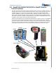
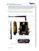
00MHz Base Unit Manual 2.1.2 SmaRT BU-9H16AF-8F-8V-RS-EXT Additional space must be considered for the base unit external antenna when mounting the BU9H16AF-8F-8V-RS-EXT. Make sure the unit is mounted so that there is a clear, unobstructed line of sight to minimize communications problems. See Figure 4 for mounting dimensions. For optional antenna extensions, please refer to Heading 4.0, Available Options. Installation of an extension antenna kit—J5-07 3ft. extension in our example—is shown in Figure 5.
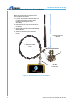
SmaRT BU-9H16AF-8F-8V-RS 2.1.3 Optional Antenna Extension Kit Installation Make sure the antenna is located in clear line-of-sight of the remote. 1. Loosen and remove extension cable nut to allow the antenna ferrule to push through a mounting hole (user discretion). 212mm (8.35”) 2. Rethread the nut to secure the ferrule to the device. 3. Attach cable extension to the BU-9H16AF8F-8V-RS-EXT. 4. Attach the antenna to the extension ferrule.
900MHz Base Unit Manual 2.1.4 SmaRT BU-9H16AF-8F-8V-RS Wiring Use the configuration diagrams supplied by Cervis as a guide when connecting the wiring harness P1 and P2 connections. Table 1 is a simplified wiring guide for two typical types of Cervis wiring harnesses. P1 Grey connector BB6-01 (HN-1001) and P2 black connector BB7-03 (HN-1002), each 12-wire cables, are numbered—marked from 1 to 11—with the last wire Yellow/Green.
SmaRT BU-9H16AF-8F-8V-RS LOAD LOAD LOAD LOAD LOAD LOAD LOAD LOAD LOAD LOAD LOAD LOAD LOAD LOAD LOAD LOAD Figure 6. BU-9H16AF-8F-8V-RS P1 and P2 Field Wiring 8 U064.
900MHz Base Unit Manual 3.0 Associate Mode Communication between the SmaRT BU-9H16AF-8F-8V-RS and SmaRT remotes is established for systems before shipped from Cervis. There may be occasions when the communication link between remote and base unit will have to be established in the field. Access to and the exact button or switch sequencing for the remote used while in Associate mode will vary depending on the type of SmaRT remote with which the base unit is to communicate.
SmaRT BU-9H16AF-8F-8V-RS 4.0 Available Options The following are some of the options available for the BU-9H16AF-8F-8V-RS-INT and BU9H16AF-8F-8V-RS-EXT base units. For custom configuration of your particular base unit and system, please consult with your Cervis Inc. sales representative. Table 2.
900MHz Base Unit Manual 5.0 Specifications Table 3. SmaRT BU-9H16AF-8F-8V-RS Specifications Item Description Power Vin +10 to +30VDC Frequency 906 – 924MHz or 2405-2480MHz (option) RF Power 10mW (max.
SmaRT BU-9H16AF-8F-8V-RS 12 U064.
900MHz Base Unit Manual Visit our Web site at: www.cervisinc.com 2011 Cervis, Inc. All rights reserved. Content is subject to change without notice. 2011 Cervis, Inc.