
User's Manual
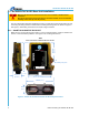
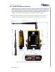


Table Of Contents

900MHz Base Unit Manual
2011 Cervis, Inc.
7
2.1.4 SmaRT BU-9H16AF-8F-8V-RS Wiring
Use the configuration diagrams supplied by Cervis as a guide when connecting the wiring
harness P1 and P2 connections. Table 1 is a simplified wiring guide for two typical types of
Cervis wiring harnesses. P1 Grey connector BB6-01 (HN-1001) and P2 black connector BB7-03
(HN-1002), each 12-wire cables, are numbered—marked from 1 to 11—with the last wire
Yellow/Green. BB7-04 (HN-1005) uses 24 bundled, uniquely colored wires that relate and
separate to the Grey P1 and Black P2 connectors. See Table 2 for particular harness options.
Figure 6 is a simplified field wiring chart that indicates generic P1 and P2 wiring.
Table 1. BU-9H16AF P1 and P2 Cable Wiring
Pin
BB6-01
Signal Name
Pin
BB7-03
Signal Name
BB7-04
BB7-04
P1:1
1
VDC+ (VBAT+)
P2:1
1
DIO 3
Red Red-Blk
P1:2
2
VDC+ (VBAT+)
P2:2
2
DIO 4
Org Org-Blk
P1:3
3
DIO 6
P2:3
3
DIO 2
Wht Wht-Blk
P1:4
4
DIO 8
P2:4
4
AIO 5
Grn Grn-Blk
P1:5
5
AIO 4
P2:5
5
AIO 7
Blu Blue-Blk
P1:6
6
AIO 2
P2:6
6
CANH/232 IN (RX)
Red-Wht Wht-Red
P1:7
7
AIO 1
P2:7
7
CANL/232 OUT (TX)
Grn-Wht Red-Wht-Blk
P1:8
8
AIO 3
P2:8
8
AIO 8
Blue-Wht Blk-Wht-Red
P1:9
9
DIO 7
P2:9
9
AIO 6
Blk-Wht Wht-Blk-Red
P1:10
10
DIO 5
P2:10
10
DIO 1
Red-Grn Blue-Red
P1:11
11
VCC– (VBAT–)
P2:11
11
VCC– (VBAT–)
Org-Grn Org-Red
P1:12
Ylw-Grn
VCC– (VBAT–)
P2:12
Ylw/Grn
VCC– (VBAT–)
Black Blk-Red