
User's Manual


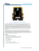
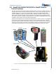
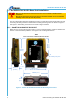
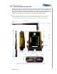
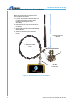
Table Of Contents

900MHz Base Unit Manual
2011 Cervis, Inc.
i
Table of Contents
List of Figures ............................................................................................................................... i
Related Documents ...................................................................................................................... ii
Cervis Inc. Safety Precautions ................................................................................................... 1
1.0 BU-9H16AF-8F-8V-RS Base Unit ........................................................................................ 2
2.0 SmaRT BU-9H16AF-8F-8V-RS in SmaRT Remote Control Systems ............................... 3
2.1 BU-9H16AF-8F-8V-RS Base Unit Installation ................................................................. 4
2.1.1 SmaRT BU-9H16AF-8F-8V-RS-INT ............................................................................ 4
2.1.2 SmaRT BU-9H16AF-8F-8V-RS-EXT ........................................................................... 5
2.1.3 Optional Antenna Extension Kit Installation ................................................................. 6
2.1.4 SmaRT BU-9H16AF-8F-8V-RS Wiring ........................................................................ 7
3.0 Associate Mode .................................................................................................................... 9
4.0 Available Options ............................................................................................................... 10
5.0 Specifications ..................................................................................................................... 11
List of Figures
Figure 1. SmaRT BU-9H16AF-8F-8V-RS-INT Base Unit .............................................................. 2
Figure 2. SmaRT BU-9H16AF-8F-8V-RS with SmaRT Remote Control Units
........................... 3
Figure 3. SmaRT BU-9H16AF-8F-8V-RS-INT Mounting Dimensions
......................................... 4
Figure 4. SmaRT BU-9H16AF-8F-8V-RS-EXT Mounting Dimensions
........................................ 5
Figure 5. Antenna Extension Kit Installation
............................................................................... 6
Figure 6. BU-9H16AF-8F-8V-RS P1 and P2 Field Wiring
............................................................ 8
List of Tables
Table 1. BU-216F-INT P1 and P2 Cable Wiring ............................................................................ 7
Table 2. Available Options
.......................................................................................................... 10
Table 3. SmaRT BU-9H16AF-8F-8V-RS Specifications
............................................................. 11