
User's Manual


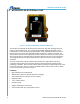
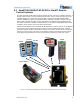
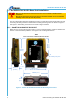
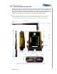
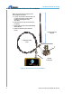
Table Of Contents

SmaRT BU-9H16AF-8F-8V-RS
U064.1-SmaRT_BU-9H16AF-8F-8V-RS
4
2.1 BU-9H16AF-8F-8V-RS Base Unit Installation
Make sure the machine to which the base unit is to be installed is disabled during
installation.
Base Units subjected to the elements must be vertically installed. Cervis recommends
installing all base unit top-side UP (vertical)
Use the configuration diagrams supplied by Cervis as a guide when mounting the base unit and
connecting the wiring harnesses. Dimensions for drilling mounting holes are shown in Figure 3
and Figure 4. Field wiring connections are shown in Figure 6 below.
2.1.1 SmaRT BU-9H16AF-8F-8V-RS-INT
Make sure the unit is mounted so that there is a clear, unobstructed line of sight to minimize the
chance of communications problems. See Figure 3 for mounting dimensions.
Figure 3. SmaRT BU-9H16AF-8F-8V-RS-INT Mounting Dimensions
BU-9H16AF-8F-8V-RS-
INT
P1 P2
102mm (4”)
center-to-center
7.4mm (0.29”) dia.
118mm (4.7”)
133mm
(5.25”)
36mm
(1.4”)
74.9mm
(2.95”)
TOP
Base unit must be installed with this end UP!
35.87mm
(1.412”)