
User's Manual


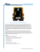
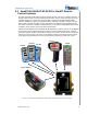
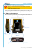
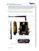
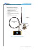
Table Of Contents

900MHz Base Unit Manual
2011 Cervis, Inc.
5
2.1.2 SmaRT BU-9H16AF-8F-8V-RS-EXT
Additional space must be considered for the base unit external antenna when mounting the BU-
9H16AF-8F-8V-RS-EXT. Make sure the unit is mounted so that there is a clear, unobstructed
line of sight to minimize communications problems. See Figure 4 for mounting dimensions. For
optional antenna extensions, please refer to Heading 4.0, Available Options. Installation of an
extension antenna kit—J5-07 3ft. extension in our example—is shown in Figure 5.
Note: The SmaRT BU-9H15AF-EXT external antenna is hinged with 0° and 90° detents so
that the antenna can be set at an 0° or 90° angle. Angles between 0° or 90° can be
achieved, but they are not firmly set and may be prone to move during equipment use.
Figure 4. SmaRT BU-9H16AF-8F-8V-RS-EXT Mounting Dimensions
BU-9H16AF-8F-
8V RS EXT
102mm (4”)
center-to-center
180mm (7.08”)
74.9mm
(2.95”)
183mm (7.2”)
P1 P2
118mm (4.7”)
36mm
(1.4”)
133mm (5.25”)
7.4mm
(0.29”) dia.
212mm (8.35”)
35.87mm
(1.412”)