CV-900 / CV-1800 / CV-2800 HEAVY DUTY PROFESSIONAL AMPLIFIERS USER MANUAL
IMPORTANT SAFETY INSTRUCTIONS 1. Read Instructions – All the safety and operating instructions should be read before this product is operated. 2. Retain Instructions – The safety and operating instructions should be retained for future reference. 10. WARNING: The mains plug or amplifier power inlet is used as a disconnet device, the disconnect device shall remain readily operable.
INTRODUCTION Thank you for your decision to purchase Cerwin-vega’s innovative new CV Series professional power amplifier! Engineered for superior sound reproduction, the CV Series line of professional amplifiers deliver top quality audio at an affordable price. The CV Series offer a standard of reliability and efficiency that makes them the perfect solution for every DJ, musician, and sound engineer.
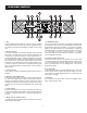
FRONT PANEL CONTROLS These blue LED's indicate that AC power is connected and the amplifier is turned on. 1. Rack Ears These ears are used to mount the amplifier in any standard 19” rack. 7. Protect Indicators These red LED's indicate that the channel is in Protect mode. When the channel goes into protect mode all output for that channel will be muted. The protect LED's light when overheating or other severe problems occur. This is to protect any speakers connected to the channel.
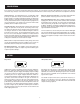
REAR PANEL CONTROLS 7. 5-way Binding Post Connect each channel of the unit to your speakers. Binding posts are provided for each channel as well as Speakon® connectors, so that paralleling of speakers is possible. Connection to the binding posts can be made with bare wire, banana plugs, or spade lug terminations. Make connections to both the Channel 1 and Channel 2 terminals for Stereo or Parallel Mode, or a single connection across the red terminals only of Channel 1 and Channel 2 for Bridged Mono Mode.
PROTECTION Every model in the CV-Series incorporates protection features. The front panel Protection LED indicates the activity of the speaker connection relay circuitry in each channel. When the protection LED turns on, this circuitry is active, and all connected speakers are muted. Initial power-up : For approximately five seconds after initial power-up, the protection circuitry is activated and the speaker outputs are muted.
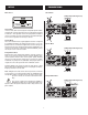
SETUP CONNECTIONS Stereo Mode Mode Select (5-Way Ouptut Binding Posts) Stereo Mode In stereo mode, both channels operate independently with individual input gain controls. Signal at channel 1’s input produces output at channel 1, while signal at channel 2’s input produces output at channel 2’s output. Recommended minimum nominal load impedance for stereo operation is 2 ohms per channel.
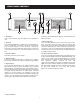
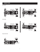
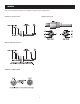
CONNECTIONS Stereo Mode SPK+ to PIN 1+ SPK- to PIN 1- SPK+ to PIN 1+ SPK- to PIN 1B B A SPK+ to PIN 1+ SPK- to PIN 1- SPK+ to PIN 2+ SPK- to PIN 2- SPK+ to PIN 1+ SPK- to PIN 1- SPK+ to PIN 1+ SPK- to PIN 1- Parallel Mode B B A SPK+ to PIN 2+ SPK- to PIN 2- SPK+ to PIN 1+ SPK- to PIN 1- Bridged Mono Mode SPK+ to PIN 1+ SPK- to PIN 2+ 8
WIRING These are several ways to interface to the amplifier to support a variety of applications.
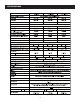
SPECIFICATIONS 10
SPEAKER COMPATIBILITY The CV Series of amplifiers are designed to work with many different speakers on the market. They have been paired with the following Cerwin-Vega speakers. The following compatibility matrix can be used as a reference. (See: www.cerwin-veg com for product specs.