CVM-1224FXUSB CVM-1624FXUSB PROFESSIONAL AUDIO MIXER (p. 2) TABLE DE MIXAGE AUDIO PROFESSIONNELLE (p. 30) MESA DE MEZCLAS PROFESIONAL (p. 58) PROFESSIONELLEN AUDIO-MIXER (S.
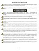
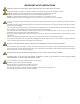
IMPORTANT SAFETY INSTRUCTIONS CAUTION: THE LIGHTNING FLASH WITH AN ARROWHEAD SYMBOL WITHIN AN EQUILATERAL TRIANGLE IS INTENDED TO ALERT THE USER TO THE PRESENCE OF UN-INSULATED DANGEROUS VOLTAGE WITHIN THE UNITS ENCLOSURE THAT MAY BE OF SUFFICIENT MAGNITUDE TO CONSTITUTE A RISK OF ELECTRIC SHOCK TO PERSONS.
IMPORTANT SAFETY INSTRUCTIONS CAUTION TO PREVENT ELECTRIC SHOCK, MATCH WIDE BLADE OF PLUG TO WIDE SLOT FULLY INSERT. ENGLISH: The apparatus shall be connected to a Mains socket outlet with a protective earthing connection. GERMAN: Das Gerät ist eine Wandsteckdose mit einem Erdungsleiter angeschlossen werden. FRENCH: L’appareil doit être connecté à une prise secteur avec connexion à la terre. SPANISH: El aparato estará conectado a una toma de red eléctrica con una conexión a tierra.
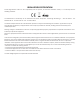
REGULATORY CERTIFICATION Cerwin-Vega declares under our sole responsibility that this product, to which this declaration relates, is in conformity with the following standards: The Declarations of Conformity can be obtained from Gibson Europe BV - Kamerlingh Onnesweg, 2 - 4131 PK Vianen - The Netherlands Tel : +31 347 32 40 10 - Fax : +31 347 32 40 15 This device complies with Part 15 of the FCC Rules.
INTRODUCTION Thank you for your decision to purchase Cerwin-Vega’s new CV Mixer Series professional audio mixer! Engineered for superior sound reproduction, the CV Mixer Series line of professional audio mixers deliver top quality audio at an affordable price. The CV Mixer Series offer a standard of reliability and efficiency that makes them the perfect solution for every DJ, musician, and sound engineer.
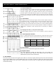
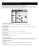
FRONT PANEL CONTROLS – CHANNEL CONTROL SECTION (1). PEAK LED INDICATOR This LED indicators lets you check the level of the signal input to the channel. The peak indicator lights when the input signal reaches 5dB below the channel’s clipping point. This indicator shows the level of the Post-EQ / pre-fader signal. If the PEAK indicator lights more than briefly on high-level transients, you should use the GAIN control to decrease the input sensitivity of the channel.
FRONT PANEL CONTROLS – CHANNEL CONTROL SECTION (continued) (8). PAN/BAL CONTROL PAN (Mono Channel) This control pans the channel signal across the master L and R buses, thus determining the perceived position of the sound from that channel in the output stereo sound field. If a PAN control is set all the way to the left, for example, the sound from that channel will be heard from the left speaker system only. If it is set all the way to the right, the sound will be heard from the right speaker system only.
FRONT PANEL CONTROLS – MAIN CONTROL SECTION (1). VFX PROGRAM DISPLAY The Program LED displays the number of the selected effects program. Use the table located above the VFX (EFX)ON/OFF switch to lookup the desired effects. (2). VFX PROGRAM SELECT SWITCH This program knob selects one of the 100 built-in digital effects, for each number you select. The VFX programs feature a 24 Bit Digital Effects processor with high quality, studio grade effects like Delay, Chorus and Reverb. (3).
FRONT PANEL CONTROLS – MAIN CONTROL SECTION (continued) (11). Level-Meter Signal Switches (MAIN-ALT 3/4 Toggle Switch and TAPE IN Switch) These level-meter switches, together with the channel PFL switches, select the signal that is sent through the CTRL ROOM/HEADPHONE control to the CONTROL ROOM out jacks, the HEADPHONE jack, and the level meter. The following illustration shows how the switch settings correspond to the signal selection. (12).
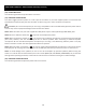
FRONT PANEL CONTROLS – MAIN CONTROL SECTION (continued) (18). POWER INDICATOR This indicator lights when the power switch is turned on. (19). PHANTOM POWER SWITCH This switch toggles phantom power on or off. If you set the switch on, the mixer supplies power to all channels that provide XLR microphone input jacks. Set this switch on when using one or more condenser microphones. WARNING, be sure the microphone you are using is compatible or will not be affected by phantom power.
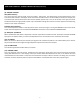
FRONT PANEL CONTROLS – INPUT/OUTPUT CONNECTORS (1). Channel Input Jacks MIC JACKS A 3-pin XLR-type connector is used for balanced low impedance microphone inputs. (pin 1: sleeve, 2: hot, 3:cold) BALANCED LINE IN JACKS A standard 1/4” phone jack is used for balanced or unbalanced line level signals. Examples of line level signals include most electronic keyboards, synthesizers, turn-tables (with appropriate pre-amps), tape decks and the line outputs from other mixers. (2).
FRONT PANEL CONTROLS – INPUT/OUTPUT CONNECTORS (continued) (5). TAPE IN JACKS These RCA pin jacks input a stereo sound source. Use these jacks when you want to connect a CD or DAT directly to the mixer for monitoring. NOTE: You can adjust the signal level using the TAPE IN control in MAIN control section. (6). REC OUT JACKS The REC OUT jacks send the pre-fader signal from the master bus for recording by the tape deck. (7). SEND JACKS * AUX: These are unbalanced phone jacks-type output jack.
REAR PANEL CONTROLS (1). AC ADAPTOR IN CONNECTOR Connects to the included power adaptor. NOTE: Use only the adaptor included with this mixer. Use of a different adaptor may result in fire or electric shock. (2). POWER SWITCH Use this switch to turn mixer power to ON or OFF. (3). MAIN L/R OUTPUT XLR JACK These jacks deliver stereo output of the mixer signal. You use these jacks, for example, to connect to the power amplifiers driving your main speakers.
USB AUDIO INTERFACE (Windows 7) 1. The first time you plug the audio mixer into a USB port, Windows will install the universal drivers for that port. A balloon tip will pop-up, telling you it recognizes the connection and will install the device driver. 4. Press ‘Mixer’ in the volume slider window to open up the Volume Mixer window. To use the audio mixer as your default output device, ensure that it is set for speakers in the Volume Mixer window by setting the default device to ‘USB Audio CODEC’. 2.
USB AUDIO INTERFACE (Windows XP) 1. The first time you plug the audio mixer into a USB port, Windows will install the universal drivers for that port. A balloon tip will pop-up, telling you it has found the USB Audio codec. 4. To use the audio mixer as your default input/output device (for system sounds and programs like Sound Recorder), ensure that it is set for playback and recording in the Properties window by setting the default device to ‘USB Audio CODEC’.
USB AUDIO INTERFACE (MAC OS X) 1. Connect the audio mixer to your MAC using a standard USB cable. The LED will light to indicate it is receiving USB power. The MAC will recognize the USB audio device and automatically install a universal driver. 4. Now, click in the Input tab and select USB Audio CODEC. You may notice that the Volume slider sets itself to the full level. This will allow you to have full range using audio mixer hardware input level controls. 2.
POINTS TO REMEMBER - In all cases, use good quality twin screened audio cable. Check for instability at the output. - Always connect both conductors at both ends, and ensure that the screen is only connected at one end. - Do not disconnect the mains earth from each piece of equipment. This is needed to provide both safety and screen returns to the system start point.
CONNECTIONS Table A (1/4” TRS) Sleeve Ring Tip Insert Balanced Line Unbalanced Line Headphones Screen Ground Ground Sleeve Return Cold (-) n/a Right Send Hot (+) Hot (+) Left Table B (XLR) Pin 1 Pin 2 Pin 3 XLR Shield/Ground Cold (-) Hot (+) 18
CONNECTIONS – CONNECTOR AND CABLE CONFIGURATIONS 19
APPLICATIONS – HOME RECORDING Setup Procedure 1. Before connecting to microphones and instruments, be sure that all devices are turned off. Also be sure that all of the mixer’s channel fader and master control faders are set all the way down. 2. For each connection, connect one end of the cable to the relevant microphone or instrument and connect the other end to the appropriate input jack on the mixer. 3.
APPLICATIONS – LIVE PERFORMANCE 21
BLOCK DIAGRAM 22
GENERAL SPECIFICATIONS *0dB=0.775Vrms, 0dBV=1VRMS +26dB (MAIN L/R), +20dB (ALT 3/4, AUX, EFX, CTRL ROOM) Maximum Output Level (0.5% T.H.D. at 1kHz) +20dB (INSERT) more than 100mW (HEADPHONES) @ 33Ω T.H.D. <0.
SPECIFICATIONS INPUT Input Connector Input Impedance Nominal Impedance Rated Input Level Connector Type CH Mic 4 kΩ 50 ~ 600 Ω -50 dB XLR 3-31 Type Balanced CH Line 10 kΩ 600 Ω -30 dB Phone Jack (TRS) T=Hot R=Cold S=GND Stereo Input Mic 3 kΩ 600 Ω -44 dB XLR 3-31 Type Balanced Stereo Input Line 5 kΩ 600 Ω -20 dB Unbalanced Phone Jack Mono Channel Insert Input 10 kΩ 600 Ω 0 dB Phone Jack (TRS) T=Out R=In S=GND Tape In 10 kΩ 600 Ω -10 dBV RCA pin Jack Output Connector Outp
WARRANTY Thank you for choosing one of Gibson Pro Audio’s brands (Stanton, KRK, or Cerwin Vega!). Your satisfaction is extremely important to us. We proudly stand behind the quality of our work and appreciate that you put your trust in us. Registering your merchandise will help us guarantee that you are kept up to date on our latest advances. To Register Merchandise Purchased from an Authorized Gibson Pro Audio Dealer in the U.S.: Please go to: http://www.gibson.com and register online.
WARRANTY (continued) THIS WARRANTY IS EXTENDED TO THE ORIGINAL RETAIL PURCHASER ONLY AND MAY NOT BE TRANSFERRED OR ASSIGNED TO SUBSEQUENT OWNERS. IN ORDER TO VALIDATE YOUR WARRANTY, AND AS A CONDITION PRECEDENT TO WARRANTY COVERAGE HEREUNDER, YOU MUST REGISTER YOUR WARRANTY WITHIN FIFTEEN (15) DAYS FOLLOWING THE ORIGINAL DATE OF PURCHASE.YOUR PROOF OF PURCHASE OR SALES RECEIPT MUST ACCOMPANY ALL REQUESTS FOR WARRANTY COVERAGE.
WARRANTY (continued) How to Obtain Warranty Service Warranty Service outside the United States: To initiate a warranty repair, please contact the Authorized Gibson Pro Audio distributor from whom you purchased your merchandise, and follow the distributor’s return/warranty policy. Warranty Service for Merchandise Purchased from an Authorized Gibson Pro Audio Dealer in the U.
GLOSSARY attenuate to reduce or make quieter. decrease the signal level auxiliary (aux) send an output signal from the mixer to supplemental equipment that provide additional capabilities. typically the feeds to the mix are implemented on rotary level controls. an aux return on the mixer is intended to connect to the output of the supplemental equipment. balance the relative levels of the left and right channels of a stereo signal.
GLOSSARY (continued) insert a break point in the signal path to allow the connection of external devices, for instance signal processors or other mixers at line level signals. Nominal levels can be anywhere between -10dBu to +6dBu, usually coming from a low impedance source. pan (pot) abbreviation of ‘panorama’: controls levels sent to left and right outputs. peaking the point at which a signal rises to its maximum instantaneous level, before falling back down again.
CVM-1224FXUSB CVM-1624FXUSB TABLE DE MIXAGE AUDIO PROFESSIONNELLE 30
MESURES DE SECURITE IMPORTANTES ATTENTION : LE SYMBOLE DE L’ÉCLAIR À L’INTÉRIEUR D’UN TRIANGLE ÉQUILATÉRAL, EST DESTINÉ À ALERTER L’UTILISATEUR DE LA PRÉSENCE DE PIÈCES SOUS TENSION NON ISOLÉES DANS LE PRODUIT, D’UNE MAGNITUDE POUVANT CONSTITUER UN RISQUE D’ÉLECTROCUTION.
MESURES DE SECURITE IMPORTANTES POUR EVITER LES CHOCS ÉLECTRIQUES, INTRODUISEZ LA LAME LA PLUS LARGE DE LA FICHE DANS LA BORNE CORRESPONDANTE DE LA PRISE ET POUSSEZ JUSQU’AU FOND. ENGLISH: The apparatus shall be connected to a Mains socket outlet with a protective earthing connection. GERMAN: Das Gerät ist eine Wandsteckdose mit einem Erdungsleiter angeschlossen werden. FRENCH: L’appareil doit être connecté à une prise secteur avec connexion à la terre.
INTRODUCTION Nous tenons à vous remercier pour votre achat d’une table de mixage audio professionnelle de la nouvelle série CV de Cerwin-Vega ! Conçu pour une reproduction sonore de qualité, la série CV de tables de mixage audio professionnelles offre un son de haute qualité à un prix abordable. La série CV de tables de mixage offre un niveau de fiabilité et d'efficacité qui en fait la solution parfaite pour tous les DJ, musiciens et ingénieurs de son.
BOUTONS DU PANNEAU AVANT - SECTION CONTROLE DE CANAL (1). TÉMOIN DE CRÊTE Ces témoins permettent de vérifier le niveau du signal d'entrée au canal. Les témoins de crête s’allument lorsque le signal d'entrée atteint 5 dB en dessous du point d'écrêtage du canal. Ces indicateurs montrent le niveau du signal après l’égaliseur et avant le fader. Si les témoins de crête restent allumés pendant les transitoires de haut niveau, vous devez diminuer la sensibilité d'entrée du canal à l’aide du bouton GAIN.
BOUTONS DU PANNEAU AVANT - SECTION CONTROLE DE CANAL (suite) (8). BOUTON PAN/BAL PAN (canal mono) Ce bouton effectue un panoramique du signal du canal à travers les bus maîtres L (gauche) et R (droite), déterminant ainsi la position du son perçu de ce canal dans le champ sonore de sortie stéréo. Si un bouton PAN est positionné à fond vers la gauche, par exemple, le son à partir de ce canal sera reproduit par le système d’enceintes gauche uniquement.
BOUTONS DU PANNEAU AVANT - SECTION DE COMMANDE PRINCIPALE (1). AFFICHAGE DU PROGRAMME VFX Les LED Programme affichent le numéro du programme d’effets sélectionné. Utilisez le tableau situé au-dessus du bouton ON/OFF VFX (EFX) pour rechercher les effets désirés. (2). BOUTON DE SÉLECTION DU PROGRAMME VFX Ce bouton programme sélectionne l'un des 100 effets numériques intégrés, pour chaque numéro que vous choisissez.
BOUTONS DU PANNEAU AVANT - SECTION DE COMMANDE PRINCIPALE (suite) (11). Boutons de signaux de sonomètre (Interrupteur à bascule MAIN-ALT 3/4 et bouton TAPE IN) Ces commutateurs de sonomètre, ainsi que les boutons PFL des canaux, sélectionnent le signal qui est envoyé par le bouton CTRL ROOM/HEADPHONE aux connecteurs de sortie CONTROL ROOM, connecteur HEADPHONE et au sonomètre. L'illustration suivante montre comment les paramètres du bouton correspondent à la sélection du signal. (12).
BOUTONS DU PANNEAU AVANT - SECTION DE COMMANDE PRINCIPALE (suite) (18). TEMOIN D'ALIMENTATION Ce témoin s'allume lorsque le bouton d’alimentation est activé. (19). BOUTON D'ALIMENTATION FANTOME Ce bouton permet d’activer/désactiver l’alimentation fantôme. Si l’alimentation fantôme est activée, la table de mixage alimente tous les canaux dotés de connecteurs XLR d'entrée micro. Activez ce bouton lorsque vous utilisez un ou plusieurs microphones à condensateur.
BOUTONS DU PANNEAU AVANT – CONNECTEURS D’ENTREE/SORTIE (1). Connecteurs d’entrée canal Connecteur MIC Un connecteur 3 broches de type XLR est utilisé pour les entrées de microphones symétriques d'impédance faible. (Broche 1 : manchon, 2 : positif, 3 : négatif) CONNECTEURS D’ENTRÉE LIGNE SYMÉTRIQUES Un connecteur téléphonique ¼" standard est utilisé pour des signaux symétriques ou asymétriques de niveau ligne.
BOUTONS DU PANNEAU AVANT – CONNECTEURS D’ENTREE/SORTIE (suite) (5). CONNECTEURS TAPE IN Il s’agit de connecteurs RCA à broches pour l'entrée d’une source sonore stéréo. Utilisez ces connecteurs lorsque pour connecter un lecteur CD ou DAT (bande audionumérique) directement à la table de mixage pour le contrôle continu. REMARQUE : Vous pouvez régler le niveau du signal en utilisant le bouton TAPE IN de la section de commande principale. (6).
BOUTONS DU PANNEAU ARRIERE (1). CONNECTEUR D’ENTREE DE L’ADAPTATEUR SECTEUR Pour brancher l’adaptateur secteur qui est fourni. REMARQUE : Utilisez uniquement l'adaptateur fourni avec cette table de mixage. Utilisation d'un adaptateur différent peut provoquer un incendie ou un choc électrique. (2). INTERRUPTEUR D'ALIMENTATION Utilisez cet interrupteur pour allumer et éteindre la table de mixage. (3).
INTERFACE AUDIO USB (Windows 7) 1. La première fois que vous branchez la table de mixage audio sur un port USB, Windows va installer les pilotes universels pour ce port. Une info-bulle apparaîtra vous indiquant qu'il reconnaît la connexion et installe le pilote de l'appareil. table de mixage en définissant l'appareil par défaut comme « CODEC audio USB ». 2. Une fois les pilotes installés, l'info-bulle va se réactualiser et vous informera que l'installation est terminée.
INTERFACE AUDIO USB (Windows XP) 1. La première fois que vous branchez la table de mixage audio sur un port USB, Windows va installer les pilotes universels pour ce port. Une info-bulle apparaîtra vous indiquant qu'il a trouvé le codec audio USB. 4.
INTERFACE AUDIO USB (MAC OS X) 1. Connectez la table de mixage audio à votre Mac via un câble USB standard. Le témoin s'allume pour indiquer qu'il est sous tension USB. Le MAC reconnaît l'appareil audio USB et installe automatiquement un pilote universel. 4. Cliquez à présent sur l'onglet Entrée et sélectionnez CODEC Audio USB. Vous remarquerez que le curseur volume est au niveau maximum. Cela vous permettra d'avoir toutes les possibilités à l'aide des boutons d'entrée de la table de mixage audio. 2.
POINTS À RETENIR - Dans tous les cas, utilisez un câble audio double blindage de bonne qualité. Vérifiez l'instabilité à la sortie. - Connectez toujours les deux conducteurs aux deux extrémités et veiller à ce que le blindage n’est connecté qu’à une extrémité. - Ne débranchez pas la mise à la terre des appareils. Ceci est nécessaire pour la sécurité et les retours de blindage au point de départ du système.
CONNEXIONS Tableau A (TRS 1/4”) Manchon Anneau Pointe Insert Ligne symétrique Ligne asymétrique Casque Blindage Terre Terre Manchon Retour Froid (-) N/A Droite Envoi Chaud (+) Chaud (+) Gauche Tableau B (XLR) Broche 1 Broche 2 Broche 3 XLR Blindage/Terre Froid (-) Chaud (+) 46
CONNEXIONS – CONFIGURATIONS DES CONNECTEURS ET DES CABLES 47
APPLICATIONS – ENREGISTREMENT À DOMICILE Procédure de Configuration : 1. Avant de connecter les microphones et les instruments, assurez-vous que tous les appareils sont éteints. Assurez-vous également que tous faders des canaux et les faders maîtres de la table de mixage sont au niveau le plus faible. 2. Pour chaque connexion, connectez une extrémité du câble au microphone ou à l'instrument correspondant et l'autre extrémité au connecteur d'entrée approprié de la table de mixage. 3.
APPLICATIONS – REPRESENTATIONS EN LIVE 49
SCHEMA DE PRINCIPE 50
SPÉCIFICATIONS GÉNÉRALES *0dB=0,775Vrms, 0dBV=1VRMS Niveau de sortie maximum +26dB (MAIN L/R), +20dB (ALT 3/4, AUX, EFX, CTRL ROOM) (0,5% TDH à 1 kHz) +20dB (INSERT) supérieur à 100mW (CASQUES) @ 33Ω T.D.H.
SPÉCIFICATIONS GÉNÉRALES ENTREE Connecteur d'entrée Impédance d'entrée Impédance nominale Niveau d'entrée nominal Type de connecteur CH Mic 4 kΩ 50 ~ 600 Ω -50 dB Type XLR 3-31 symétrique CH Line 10 kΩ 600 Ω -30 dB Connecteur téléphonique (TRS) T=+ R=- S=GND Entrée micro stéréo 3 kΩ 600 Ω -44 dB Type XLR 3-31 symétrique Entrée ligne stéréo 5 kΩ 600 Ω -20 dB Entrée Insert canal mono 10 kΩ 600 Ω 0 dB Tape In 10 kΩ 600 Ω -10 dBV Connecteur RCA à broches Connecteur de sortie I
GARANTIE Nous vous remercions d'avoir choisi l'une des marques Gibson Pro Audio (Stanton, KRK et Cerwin Vega!). Votre satisfaction est extrêmement importante pour nous. Nous sommes fiers d’être derrière la qualité de notre travail et nous apprécions que vous mettiez votre confiance en nous. L'enregistrement de votre produit nous aidera à garantir que vous êtes tenu au courant de nos dernières améliorations.
GARANTIE (suite) CETTE GARANTIE N’EST ACCORDEE QU’A L'ACHETEUR AU DETAIL ORIGINAL ET NE PEUT ETRE TRANSFEREE OU CONCEDEE AUX PROPRIETAIRES ULTERIEURS. AFIN DE VALIDER VOTRE GARANTIE, EN TANT QUE CONDITION NECESSAIRE POUR BENEFICIER DE LA GARANTIE, VOUS DEVEZ ENREGISTRER VOTRE GARANTIE DANS LES QUINZE (15) JOURS SUIVANT LA DATE INITIALE DE L'ACHAT. LA FACTURE OU REÇU D'ACHAT DOIT ACCOMPAGNER TOUTES LES DEMANDES D’INTERVENTION SOUS GARANTIE.
GARANTIE (suite) Comment obtenir un service au titre de la garantie Service de garantie en dehors des États-Unis: Pour initier une réparation sous garantie, contactez le revendeur agréé Gibson Pro Audio auprès duquel vous avez acheté votre produit et suivez les règles de retour/garantie de ce dernier.
GLOSSAIRE atténuer Réduire ou rendre plus silencieux ; diminuer le niveau du signal auxiliaire (AUX) Envoyer un signal de sortie de la table de mixage à un équipement complémentaire qui fournit des fonctions supplémentaires. Généralement les flux de mixage sont implémentés par des boutons de contrôle de niveau rotatifs. Un retour à la table de mixage consiste à connecter la sortie de l'équipement supplémentaire. balance Il s'agit des niveaux relatifs des canaux gauche et droite d'un signal stéréo.
GLOSSAIRE (suite) insert Un point de rupture dans le trajet du signal pour permettre la connexion de dispositifs externes, des processeurs de signaux par exemple ou d'autres table de mixages à des signaux de niveau ligne. Les niveaux nominaux peuvent être n'importe où entre -10 dBu à +6 dBu, généralement provenant d'une source à faible impédance. pan (potentiomètre) Abréviation de « panoramique » : contrôle les niveaux envoyés vers les sorties gauche et droite.
CVM-1224FXUSB CVM-1624FXUSB MESA DE MEZCLAS PROFESIONAL 58
INSTRUCCIONES DE SEGURIDAD IMPORTANTES PRECAUCIÓN: EL SÍMBOLO DE RELÁMPAGO CON PUNTA DE FLECHA DENTRO DE UN TRIÁNGULO EQUILÁTERO ADVIERTE AL USUARIO DE LA PRESENCIA DE UNA “TENSIÓN PELIGROSA” NO AISLADA DENTRO DE LA CARCASA DEL SISTEMA QUE PUEDE SER DE UNA MAGNITUD SUFICIENTE COMO PARA CONSTITUIR UN RIESGO DE DESCARGA ELÉCTRICA PARA LAS PERSONAS.
INSTRUCCIONES DE SEGURIDAD IMPORTANTES PARA EVITAR CHOQUES DESCARGAS ELÉCTRICAS, HAGA COINCIDIR LA HOJA ANCHA DEL ENCHUFE CON LA RANURA ANCHA LA TOMA DE CORRIENTE E INSÉRTELA COMPLETAMENTE. ENGLISH: The apparatus shall be connected to a Mains socket outlet with a protective earthing connection. GERMAN: Das Gerät ist eine Wandsteckdose mit einem Erdungsleiter angeschlossen werden. FRENCH: L’appareil doit être connecté à une prise secteur avec connexion à la terre.
INTRODUCCIÓN ¡Le agradecemos la decisión de comprar la nueva mesa de mezclas profesional de la serie CV Mixer de Cerwin-Vega! Diseñada para una reproducción superior del sonido, la línea de mesas de mezclas profesionales de la serie CV Mixer proporciona audio de máxima calidad a un precio asequible. La serie CV Mixer ofrece un estándar de fiabilidad y eficiencia que la hacen ser la solución perfecta para cualquier DJ, músico e ingeniero de sonido.
CONTROLES DEL PANEL FRONTAL – SECCIÓN DE CONTROL DE CANALES (1). INDICADOR LED DE PICOS Este indicador LED le permite comprobar el nivel de la señal de entrada al canal. El indicador de picos se ilumina cuando la señal de entrada alcanza 5dB por debajo del umbral de saturación del canal. Este indicador muestra el nivel de la señal Post-EQ /Pre-Fader.
CONTROLES DEL PANEL FRONTAL – SECCIÓN DE CONTROL DE CANALES (Cont.) (8). CONTROL PAN / BAL PAN (Canal Mono) Este control criba la señal del canal a través de los buses maestros Izdo. y Dcho., determinando así la posición de percepción del sonido desde ese canal en el campo de sonido estéreo de salida. Si el control PAN está ajustado todo a la izquierda, por ejemplo, el sonido desde ese canal se oirá solamente desde el sistema de altavoces izquierdo.
CONTROLES DEL PANEL FRONTAL – SECCIÓN DE CONTROL PRINCIPAL (1). PRESENTACIÓN DEL PROGRAMA VFX La pantalla LED del programa le muestra el número del programa de efectos seleccionado. Use la tabla situada sobre el interruptor ‘VFX (EFX) ON’ para buscar los efectos deseados. (2). INTERRUPTOR DE SELECCIÓN DEL PROGRAMA VFX Este control selecciona uno de los 100 efectos digitales integrados, según el número que seleccione.
CONTROLES DEL PANEL FRONTAL – SECCIÓN DE CONTROL PRINCIPAL (cont.) (11). Interruptores de señal del Medidor de nivel (Conmutador ‘MAIN-ALT 3/4’ E INTERRUPTOR ‘TAPE IN’ Estos interruptores del medidor de nivel, junto con los interruptores PFL de canal, seleccionan la señal que se envía a través del control ‘CTRL ROOM/HEADPHONE’ a las salidas de la CABINA DE CONTOL, AURICULARES, y al medidor de nivel.
CONTROLES DEL PANEL FRONTAL – SECCIÓN DE CONTROL PRINCIPAL (cont.) (18). INDICADOR ENCENDIDO (‘POWER’) Este indicador se ilumina cuando el interruptor de alimentación activado. (19). INTERRUPTOR DE CORRIENTE FANTASMA (‘PHANTOM’) Este interruptor activa o desactiva la alimentación fantasma. Si coloca el interruptor en la posición de encendido, el mezclador suministra alimentación a todos los canales con conectores XLR de entrada de micrófono.
CONTROLES DEL PANEL FRONTAL – CONECTORES DE ENTRADA/SALIDA (1). Conectores de entrada de canal CONECTORES ‘MIC’ Un conector de 3 pines tipo XLR que se usa para las entradas de de micrófonos de baja impedancia balanceados. (Pin 1: Pantalla, 2: positivo, 3: negativo) CONECTORES BALANCEADOS DE ENTRADA DE LÍNEA Un conector de auriculares de ¼” estándar que se usa para señales de nivel de línea balanceadas o desbalanceadas.
CONTROLES DEL PANEL FRONTAL – CONECTORES DE ENTRADA/SALIDA (cont.) (5). CONECTORES ‘TAPE IN’ Estos conectores de pines RCA introducen una fuente de sonido estéreo. Use estos conectores cuando desee conectar un CD o DAT directamente a la mesa de mezclas para su monitorización. NOTA: Puede ajustar el nivel de señal usando el control ‘TAPE IN’ en la sección de control PRINCIPAL. (6).
CONTROLES DEL PANEL TRASERO (1). CONECTOR ELÉCTRICO ‘AC ADAPTOR IN’ Se conecta el adaptador eléctrico incluido. NOTA: Utilice únicamente el adaptador incluido con esta mesa de mezclas. Usar otro adaptador diferente puede provocar un incendio o una descarga eléctrica. (2). INTERRUPTOR DE ENCENDIDO ‘POWER’ Use este interruptor para ENCENDER o APAGAR la mesa de mezclas. (3). CONECTORES Izdo./Dcho. de salida ‘MAIN OUTPUT’ Estos conectores distribuyen la salida estéreo del la señal de la mesa de mezclas.
INTERFAZ DE AUDIO USB (Windows 7) 1. La primera vez que conecte la mesa de mezclas de audio en un puerto USB, Windows instalará los controladores universales para ese puerto. Aparecerá un cuadro de diálogo emergente, diciéndole que se reconoce la conexión y que se instalará el controlador del dispositivo. dispositivo por defecto para los altavoces en la ventana del Mezclador de Volumen. 2.
INTERFAZ DE AUDIO USB (Windows XP) 1. La primera vez que conecte la mesa de mezclas de audio en un puerto USB, Windows instalará los controladores universales para ese puerto. Un cuadro de diálogo le aparecerá, diciéndole que se ha encontrado el ‘USB Audio Codec’. 4.
INTERFAZ DE AUDIO USB (MAC OS X) 1. Conecte la mesa de mezclas a su MAC usando un cable USB estándar. El LED se iluminará indicando que está recibiendo alimentación USB. El MAC reconocerá automáticamente el dispositivo de audio y automáticamente instalará un controlador universal. 4. Ahora, haga ‘clic’ en la pestaña de Entrada y seleccione ‘USB Audio CODEC’. Puede comprobar que el control deslizante del volumen se coloca al nivel máximo.
PUNTOS PARA RECORDAR - En todos los casos, use un cable de audio con doble apantallamiento de buena calidad. Compruebe la estabilidad de la salida. - Conecte siempre ambos conductores en ambos terminales, y asegúrese de que la conexión a tierra se establece solamente en uno de los terminales. - No desconecte la toma de tierra en ninguno de los elementos del equipo. Es necesario proporcionar tanto seguridad como apantallamiento en el punto de inicio del sistema.
CONEXIONES Tabla A (1/4” TRS) Manga Anillo Punta Inserción Línea balanceada Línea desbalanceada Auriculares Pantalla Tierra Tierra Camisa Retorno Negativo (-) Sin valor Derecho Envío Positivo (+) Positivo (+) Izquierdo Tabla B (XLR) Pin 1 Pin 2 Pin 3 XLR Pantalla/Tierra Negativo (-) Positivo (+) 74
CONEXIONES – CONFIGURACIONES DEL CONECTOR Y CABLE 75
APLICACIONES – GRABACIONES DOMÉSTICAS Procedimiento de configuración 1. Antes de conectar los micrófonos e instrumentos, cerciórese de que todos los dispositivos están apagados. Asegúrese también de que todos los faders de canal y de control maestro están al mínimo. 2. Para cada conexión, conecte un extremo del cable al micrófono o instrumento pertinente y conecte el otro extremo al conector de entrada apropiado en la mesa de mezclas. 3.
APLICACIONES – ACTUACIONES EN DIRECTO 77
DIAGRAMA DE BLOQUES 78
ESPECIFICACIONES GENERALES *0dB=0.775Vrms, 0dBV=1VRMS +26dB (‘MAIN L/R’), +20dB (‘ALT 3/4’, ‘AUX’, ‘EFX’, ‘CTRL ROOM’) Nivel de salida máximo (0.5% T.H.D. a 1kHz) +20dB (‘INSERT’) más de 100mW (‘HEADPHONES’) @ 33Ω <0.1% @ +14dB 20Hz~20kHz (‘MAIN L/R’, ‘ALT 3/4’, ‘AUX SEND’, ‘EFX SEND’, ‘CTRL T.H.D.
ESPECIFICACIONES ENTRADA Conector de entrada Impedancia de entrada Impedancia nominal Nivel nominal de entrada Tipo de conector Canal Mic 4 kΩ 50 ~ 600 Ω -50 dB XLR 3-31 tipo balanceado Canal Line 10 kΩ 600 Ω -30 dB Clavija de auriculares (TRS) Punta=(+) Anillo=(-) S=Tierra Entrada Mic.
GARANTÍA Gracias por elegir una de las marcas de Gibson Pro Audio (Stanton, KRK o Cerwin Vega!). Su satisfacción es muy importante para nosotros. Nosotros permanecemos con agrado tras la calidad de nuestro trabajo y apreciamos que usted confíe en nosotros. Registrando su mercancía nos ayudará a garantizarle que estará actualizado con nuestros últimos avances. Para registrar la mercancía comprada en un punto de venta autorizado Gibson Pro Audio en los EE.UU.: Por favor, entre en el sitio Web: “http://www.
GARANTÍA (continuación) Gibson garantizará todas las piezas de repuesto y las reparaciones durante noventa (90) días desde la fecha del envío original.
GARANTÍA (continuación) Cómo obtener Servicio por Garantía Servicio de Garantía fuera de los Estados Unidos. Para iniciar una reparación por garantía, por favor contacte con su distribuidor autorizado Gibson Pro Audio al que le compró la mercancía, y cumpla con la política de devolución/garantía del distribuidor. Servicio por garantía de la mercancía comprada en un punto de venta autorizado Gibson Pro Audio en los EE.UU.
GLOSARIO Atenuar Reducir o hacer más silencioso. Bajar el nivel de señal Auxiliar (aux) Enviar una señal de salida desde la mesa de mezclas a un equipo suplementario que proporciona capacidades adicionales. Normalmente las señales se implementan mediante controles de nivel giratorios. Un retorno aux en la mesa de mezclas se usa para conectarla a la salida del equipo suplementario. Balance Los niveles relativos de los canales izquierdo y derecho de una señal estéreo.
GLOSARIO (continuación) Inserción Punto de ruptura en la ruta de la señal para permitir la conexión de dispositivos externos, por ejemplo procesadores de señal u otras mesas de mezcla en las señales de nivel de línea. Los niveles nominales pueden ser cualquiera entre -10dBu hasta +6dBu, normalmente procedentes de una fuente de baja impedancia. pan (pot) Abreviatura de ‘panorama’: controla los niveles enviados a las salidas izquierda y derecha.
CVM-1224FXUSB CVM-1624FXUSB PROFESSIONELLEN AUDIO-MIXER 86
WICHTIGE SICHERHEITSHINWEISE VORSICHT: DER BLITZ IM GLEICHSEITIGEN DREIECK SOLL DEN BENUTZER VOR NICHT ABGESCHIRMTER GEFÄHRLICHER SPANNUNG WARNEN, DIE IM INNEREN DES GERÄTS VORHANDEN IST UND ZU EINEM STROMSCHLAG FÜHREN KANN. ACHTUNG: DAS AUSRUFEZEICHEN INNERHALB DES GLEICHSEITIGEN DREIECKS SOLL DEN BENUTZER AUF WICHTIGE WARTUNGSANWEISUNGEN IN DER BEILIEGENDEN DOKUMENTATION AUFMERKSAM MACHEN.
WICHTIGE SICHERHEITSHINWEISE ACHTUNG. UM ELEKTROSCHOCKS ZU VERMEIDEN, STECKEN SIE DEN STROMVERSORGUNGSSTECKER VOLLSTÄNDIG IN DIE STECKDOSE.. ENGLISH: The apparatus shall be connected to a Mains socket outlet with a protective earthing connection. GERMAN: Das Gerät ist eine Wandsteckdose mit einem Erdungsleiter angeschlossen werden. FRENCH: L’appareil doit être connecté à une prise secteur avec connexion à la terre. SPANISH: El aparato estará conectado a una toma de red eléctrica con una conexión a tierra.
EINFÜHRUNG Wir danken Ihnen, dass Sie sich für die neue professionelle Audiomischpultserie CV von Cerwin-Vega entschieden haben! Für eine phantastische Klangwiedergabe entwickelt, bietet die professionelle CV Audiomischpulteserie beste Klangqualität zu einem erschwinglichen Preis. Die CV Mischpultserie bietet einen Standard für Zuverlässigkeit und Effizienz, welcher sie zu idealen Lösung für jeden DJ, Musiker und Toningenieur macht.
BEDIENELEMENTE GERÄTEVORDERSEITE – KANAL-KONTROLLABSCHNITT (1). PEAK-LED-ANZEIGE Mit dieser LED Anzeige können Sie den Pegel des Eingangssignals zum Kanal prüfen. Die Peak-Anzeige leuchtet auf, wenn das Eingangssignal 5dB unter dem Clipping-Punkt des Kanals liegt. Diese Anzeige zeigt den Pegel des Post-EQ/Pre-Fadersignals an. Wenn die PEAK-Anzeige bei hohen Transienten länger aufleuchtet, müssen Sie den GAIN-Regler benutzen, um die Eingangsempfindlichkeit des Kanals zu verringern.
BEDIENELEMENTE GERÄTEVORDERSEITE – KANAL-KONTROLLABSCHNITT (Fortsetzung) (8). PAN/BAL-REGLER PAN (Mono-Kanal) Dieser Regler schwenkt das Kanalsignal zwischen Masterbus-L und -R, folglich bestimmt er die wahrgenommene Klangposition dieses Kanals im Ausgangs-Stereoklangfeld. Wenn beispielsweise ein PAN-Regler ganz nach links eingestellt ist, wird der Ton jenes Kanals nur vom linken Lautsprechersystem ausgegeben.
BEDIENELEMENTE GERÄTEVORDERSEITE – MAIN-REGLERABSCHNITT (1). VFX-PROGRAMMANZEIGE Die Programm-LED zeigt die Nummer des ausgewählten Effektprogamms an. Verwenden Sie die Tabelle über der VFX (EFX) ON/OFF-Taste, um die gewünschten Effekte zu suchen. (2). VFX PROGRAMM-AUSWAHLSCHALTER Dieser Programmauswahlschalter wählt die Nummer eines der 100 integrierten digitalen Effekte.
BEDIENELEMENTE GERÄTEVORDERSEITE – MAIN-REGLERABSCHNITT (Fortsetzung) (11). Pegelanzeigen-Signaltasten (MAIN-ALT 3/4-Umschalter und TAPE IN-Taste) Diese Pegelanzeigentasten wählen zusammen mit den Kanal-PFL-Tasten das Signal aus, das über das CTRL ROOM/HEADPHONE-Regler an die CONTROL ROOM-Buchsen, die HEADPHONE-Buchse und die Pegelanzeige gesendet wird. Die folgenden Abbildungen zeigen die Tasteneinstellungen entsprechend zur Signalauswahl. (12).
BEDIENELEMENTE GERÄTEVORDERSEITE – MAIN-REGLERABSCHNITT (Fortsetzung) (18). BETRIEBSANZEIGE Die Anzeige leuchtet auf, wenn der Netzschalter eingeschaltet wurde. (19). PHANTOMSPEISUNGSTASTE Die Taste schaltet die Phantomspeisung ein oder aus. Wenn Sie die Taste einschalten, versorgt das Mischpult alle Kanäle mit Strom, die XLR-Mikrofoneingangsbuchsen besitzen. Schalten Sie diese Taste ein, wenn Sie ein oder mehrere Kondensatormikrofone verwenden.
BEDIENELEMENTE GERÄTEVORDERSEITE – EIN-/AUSGANGSANSCHLÜSSE (1). Kanaleingangsbuchsen MIC-BUCHSEN Für symmetrische niederohmige Mikrofoneingänge wird eine 3-polige XLR-Buchse verwendet. (Pin 1: Mantel, 2: heiß, 3: kalt) SYMMETRISCHE LINE IN-EINGANGSBUCHSEN Für symmetrische oder unsymmetrische Signale mit Line-Pegel wird eine standardmäßige 6,3 mm-Klinkenbuchse verwendet.
BEDIENELEMENTE GERÄTEVORDERSEITE – EIN-/AUSGANGSANSCHLÜSSE (Fortsetzung) (5). TAPE IN-BUCHSEN An diese RCA-Buchse wird eine Stereo-Tonquelle angeschlossen. Verwenden Sie diese Buchsen, wenn Sie einen CDoder DAT-Player zur Überwachung direkt am Mischpult anschließen möchten. HINWEIS: Sie können den Signalpegel mittels des TAPE IN-Reglers im MAIN-Reglerabschnitt einstellen. (6). REC OUT-BUCHSEN Die REC OUT-Buchsen senden das Pre-Fadersignal vom Masterbus zur Aufnahme durch das Tapedeck. (7).
BEDIENELEMENTE AUF DER GERÄTERÜCKSEITE (1). NETZADAPTER-EINGANGSANSCHLUSS Anschluss des mitgelieferten Netzadapters. HINWEIS: Verwenden Sie nur den Adapter, der mit diesem Mischpult mitgeliefert wurde. Die Verwendung eines anderen Netzadapters kann zu einem Feuer oder Stromschlag führen. (2). POWER-SCHALTER Schalten Sie mit diesem Schalter das Mischpult ein (ON) oder aus (OFF). (3). MAIN L/R-AUSGANGSBUCHSEN XLR Diese Buchsen liefern das Stereoausgangssignal des Mischpults.
USB-AUDIOSCHNITTSTELLE (Windows 7) 1. Wenn Sie das Audiomischpult das erste Mal an einen USB-Port anschließen, installiert Windows den universellen Treiber für den Port. Ein Balloon-Tip öffnet sich und weist Sie darauf hin, dass es die Verbindung erkennt und den Gerätetreiber installieren wird. Lautstärkemixerfenster auf „USB Audio CODEC“ eingestellt ist. 2.
USB-AUDIOSCHNITTSTELLE (Windows XP) 1. Wenn Sie das Audiomischpult das erste Mal an einen USB-Port anschließen, installiert Windows den universellen Treiber für den Port. Ein Balloon-Tip öffnet sich und weist Sie darauf hin, dass ein USB-Audiocodec gefunden wurde. Standardeingabe-/Ausgabegerät zu verwenden (für Systemklänge und Programme, wie den Audiorecorder), achten Sie darauf, dass im Eigenschaftenfenster das Standardgerät für Wiedergabe und Aufnahme auf „USB Audio CODEC“ eingestellt ist.
USB-AUDIOSCHNITTSTELLE (MAC OS X) 1. Schließen Sie das Audiomischpult mittels eines gewöhnlichen USB-Kabels an Ihren MAC an. Die LED leuchtet auf, dass die USB angeschlossen ist. Der MAC erkennt das USB-Audiogerät und installiert automatisch einen universellen Treiber. 4. Klicken Sie jetzt in die Eingangsregisterkarte und wählen Sie den USB Audio CODEC. Sie dürfen bemerkt haben, dass sich der Lautstärkeschieberegler selbstständig auf den vollen Pegel eingestellt hat.
WICHTIGE PUNKTE - Verwenden Sie auf alle Fälle hochwertige Audiokabel mit doppelter Abschirmung. Prüfen Sie auf Instabilitäten am Ausgang. - Verbinden Sie stets beide Litzen an beiden Enden und achten Sie darauf, dass die Abschirmung nur an einem Ende angeschlossen ist. - Schließen Sie die Haupterdleitung nicht an jedem Gerät an. Dies wird sowohl für die Sicherheit als auch als Abschirmungsreturn zum Systemstartpunkt benötigt.
ANSCHLÜSSE Tabelle A (6,3 mm TRS) Mantel Ring Spitze Insert Symmetrische Leitung Unsymmetrische Leitung Kopfhörer Schirm Masse Masse Mantel Return Kalt (-) nicht verfügbar Rechts Send Heiß (+) Heiß (+) Links Tabelle B (XLR) Pin 1 Pin 2 Pin 3 XLR Abschirmung/Masse Kalt (-) Heiß (+) 102
ANSCHLÜSSE – VERBINDER UND KABELKONFIGURATIONEN 103
ANWENDUNGEN – HEIM-AUFNAHME Setupverfahren 1. Achten Sie vor dem Anschluss der Mikrofone und Instrumente darauf, dass alle Geräte ausgeschaltet sind. Stellen Sie auch sicher, dass alle Kanalfader und Masterregelungsfader des Mischpults heruntergezogen wurden. 2. Schließen Sie für jeden Anschluss ein Ende des Kabels an das entsprechende Mikrofon oder Instrument und das andere Ende an die entsprechende Eingangsbuchse am Mischpult an. 3.
ANWENDUNGEN – LIVE-PERFORMANCE 105
BLOCKDIAGRAMM 106
ALLGEMEINE TECHNISCHE DATEN *0 dB=0,775 Vrms, 0 dBV=1 VRMS Maximaler Ausgangspegel (0,5% T.H.D. bei 1 kHz) T.H.D.
TECHNISCHE DATEN EINGANG Eingangsanschluss Eingangsimpedanz Nennimpedanz Nenneingangspegel Anschlussart CH Mic 4 kΩ 50 - 600 Ω -50 dB XLR 3-31 symmetrisch CH Line 10 kΩ 600 Ω -30 dB Klinkenstecker (TRS) T = heiß R = kalt S = Masse Stereoeingang Mic 3 kΩ 600 Ω -44 dB XLR 3-31 symmetrisch Stereoeingang Line 5 kΩ 600 Ω -20 dB Monokanal Inserteingang 10 kΩ 600 Ω 0 dB Tape In 10 kΩ 600 Ω -10 dBV RCA-Buchse Ausgangsanschluss Ausgangsimpedanz Nennimpedanz Nennausgangspegel MAI
GARANTIE Vielen Dank, dass Sie sich für eine der Gibson Pro Audio Marken (Stanton, KRK, oder Cerwin Vega!) entschieden haben. Ihre Zufriedenheit ist uns besonders wichtig. Wir stehen voll und ganz hinter der Qualität unserer Arbeit und freuen uns, dass Sie uns vertrauen. Die Registierung Ihrer Waren hilft uns, zu garantieren, dass Sie auf dem neuesten Stand bezüglich unserer neuesten Fortschritte bleiben.
GARANTIE (Fortsetzung) DIESE GARANTIE WIRD NUR AUF DEN ORIGINAL WIEDERVERKÄUFER AUSGEWEITET UND KANN NICHT AUF NACHFOLGENDE BESITER ÜBERTRAGEN ODER DIESEN ÜBEREIGNET WERDEN. UM IHRE GARANTIE ZU VALIDIEREN UND AS EINE BEDINGUNG; DIE DER HIER VORANGEGANGENEN GARANTIEABDECKUNG; MÜSSEN SIE IHRE GARANTIE INNERHALB VON VIERZEHN (14) TAGEN NACH DEM ORIGINALKAUFDATUM REGISTIEREN LASSEN. IHR KAUFBELEG ODER IHRE VERKAUFSQUITTIUNG MUSS ALLEN ANFRAGEN FÜR GARANTIEABDECKUNG BEIGEFÜGT WERDEN.
GARANTIE (Fortsetzung) Wie erhält man eine Garantieleistung? Garantieleistung außerhalb der USA. Für eine Garantiereparatur wenden Sie sich bitte an den autorisierten Gibson Pro Audio Händler, wenden Sie sich bitte an den autorisierten Gibson Pro Audio Händler, von dem Sie Ihre Ware gekauft haben und befolgen Sie die Rücksende-/Garantiepolitik des Händlers. Garantieleistungen für von einem autorisierten Gibson Pro Audio Händler in den USA gekaufte Ware zu registrieren.
GLOSSAR Abschwächen Verringern oder leiser stellen. Die Signalhöhe verringern. Auxiliary (AUX) Sendet ein Ausgangssignal vom Mischpult zu weiteren Geräten, die zusätzliche Fähigkeiten bieten. Normalerweise werden die Feeds zum Mix mit Drehpegelreglern durchgeführt. Ein Aux-Return am Mischpult dient zum Anschluss des Ausgangs von zusätzlichen Geräten. Balance Die relativen Pegel der linken und rechten Kanäle eines Stereosignals.
GLOSSAR (Fortsetzung) Insert Ein Unterbrechungspunkt im Signalpfad, der den Anschluss externer Vorrichtungen zulässt, z. B. Signalprozessoren oder andere Mischpulte mit Linepegelsignalen. Nominalpegel können zwischen -10 dBu bis + 6 dBu liegen und kommen gewöhnlich von einer Quelle mit niedriger Impedanz. Pan (Pot) Abkürzung von „Panorama“: Kontrolle der Pegel, die an die linken und rechten Ausgänge gesendet werden.
Note(s): Remarque(s): Nota(s): Hinweise: 114
Note(s): Remarque(s): Nota(s): Hinweise: 115
CERWIN-VEGA! IS A REGISTERED TRADEMARK OF CERWIN-VEGA, LLC. CERWIN-VEGA! EST UNE MARQUE DÉPOSÉE DE CERWIN-VEGA, LLC. CERWIN-VEGA! ES UNA MARCA COMERCIAL REGISTRADA DE CERWIN-VEGA, LLC. CERWIN-VEGA! LST EN REGISTRIERTES WARENZEICHEN VON CERWIN-VEGA, LLC. CVM-1224FXUSB, CVM-1624FXUSB REV C © 2012 CERWIN-VEGA, LLC. A member of the Gibson family of brands. Membre de la famille des marques Gibson. Miembro de la familia de marcas Gibson. Ein Mitglied der Gibson-Markenfamilie. This document is copyright protected.