GPS-206 USER MANUAL CES WIRELESS TECHNOLOGIES, CORP. 925-122 South Semoran Boulevard Winter Park, Florida 32792 May 5, 2011 GPS206 Manual v3p0.doc Revision 3.0 © Copyright CES WIRELESS TECHNOLOGIES CORP. (2011) The information contained in this document is subject to change without notice and should not be construed as a commitment by CES WIRELESS TECHNOLOGIES CORP. unless such commitment is expressly given in a covering document.
REGULATORY COMPLIANCE FCC The GPRS modem was tested and certified to meet FCC Parts 15 in a stand-alone configuration, which demonstrated that it complies with Part 15 emission limits. The GPS-206 uses an Enfora manufactured GPRS modem. FCC Part 22 & Part 24 is covered by the "modular approval" process for a transmitter.
CHANGE LOG Date Author 2010-10-01 Doug Hamilton 2010-10-19 2011-05-05 Doug Hamilton Doug Hamilton Description Added this Change Log. Added description of the LEDs in Section 1.6 3.6.2: Changed descriptive requirements for the Garmin interface.
TABLE OF CONTENTS REGULATORY COMPLIANCE ...............................................................................................................2 CHANGE LOG...........................................................................................................................................3 TABLE OF CONTENTS.............................................................................................................................4 TABLE OF FIGURES................................................
TABLE OF FIGURES Figure 1: Front View of the GPS-206. Note the SIM Card Access..............................................................8 Figure 2: Back View of the GPS-206..........................................................................................................8 Figure 3: Mounting dimensions of a GPS-206...........................................................................................10 Figure 4: 8-Pin Connections.................................................................
WARRANTY Complete Warranty details can be found at the CES Wireless web site: www.ceswireless.com CES Wireless Technologies Corp., (CES Wireless), warrants this product to be free from defects in material and workmanship for 12 months from date of shipment. If such malfunction occurs, it will be repaired or replaced (at our option) without charge for materials or labor if returned to the factory.
1.0 Introduction The GPS-206 is one of the smallest and most economical GPS asset tracking devices available today. This device is neither weather, dust or splash proof. GPS and event data is made available on-board the GPS-206 for transmission to FleetLinc (CES web based subscriber fleet management service). The GPS-206 can also be licensed for use with POWER-trak™ PC/Server software. Please contact CES for further direction with this. 1.
USR1 (Green) – This LED indicates the state of the GSM connection. If blinking the GPS206 is attempting to establish the connection. If solid the GSM connection has been established. PWR GPS (Red) – When this LED is illuminated it indicates that the GPS206 has power. USR2 (Red) – This LED indicates the state of the GPS fix. If illuminated the GPS206 has established a position fix from satellites in the GPS satellite constellation that are viewable from its current location.
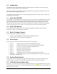
2.0 Specifications Note: Specifications subject to change without notice. 2.1 System Information Dimensions Weight Housing: TX Power: 64.8 x 61 x 25.6mm L x W x H: Rugged plastic enclosure Class 4 (2W @850/900 MHz) Class 1 (1W @1800/1900 MHz) 850/900/1800/1900 Frequency: 2.2 GPRS Packet Data Mode: Protocol: Coding Schemes: Packet Channel: 2.3 Class B, Multislot 10 GSM/GPRS Rel 97 AMR Rel 99 CS1-CS4 PBCCH/PCCCH GPS Functionality Connector: Antenna: 2.4 Fakra 3.
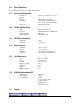
GSM 1800/1900 2.8 Idle <40 1TX/RX 215 Idle <40 1.3 Battery Specifications The GPS-206 uses power either from the vehicle battery, or from an optional internal battery. The battery specifications are as follows: Nominal voltage: 3.6 VDC Nominal Capacity: 230 mAH when discharged at 46mA to 2.5V Maximum and Normal Charge voltage Minimum discharge voltage: Charge current: 3.0 4.2 V 2.5V 100mA Installation The instructions in this section describe the hardware installation of the GPS-206.
The GPS-206 should be used as a template to mark screw holes for installation. The mounting holes are designed for a number 8 screw. 3.2 Installing Cables To ensure proper operation of the GPS-206 please follow these precautions: • • • • • Remove power from the GPS-206. Do not create sharp bends, loops or crimps in the cables. Attach all cables to the vehicle and equipment in such a way as to reduce stress or wear caused by the vibration generated by moving vehicles.
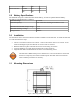
Figure 4: 8-Pin Connections The manufacturer part numbers for the parts needed to build the cables is noted in the following table. Item Connector Pins Manufacturer Molex Molex Crimp Tool Molex Part Number 43025-0800 43030-0008 20-24 AWG 43030-0011 26-30 AWG 63819-0000A Table 2: Manufacturer Part Numbers to Build Cables 3.3 Installing the SIM (Subscriber Identity Module) Card The SIM card is an integral part of any GSM terminal device.
• ANT-13 Loose/covert, combo, multi band GSM/GPS antenna • • • ANT-19 ANT-01 ANT-02 Fixed mount, GSM only antenna Magnetic mount, GPS only antenna Fixed mount, GPS only antenna - The GSM/GPRS antenna connector on the GPS-206 is a FAKRA Bordeaux Violet Coding D antenna connector. The antenna must be connected to the connector labeled “GSM”. - The GPS antenna connector on the GPS-206 is a FAKRA Blue Coding C Antenna Connector. The antenna must be connected to the connector labeled “GPS”.
A Garmin Nüvi Personal Navigation Device (PND) may be used in conjunction with the GPS-206 providing the capability to 1. Send text messages from the PND to the host application (i.e. PT3) • Text messages can be entered on the PND using its on screen keyboard and then sent to the host application. 2. Receive text messages from the host application • A text message can be entered in the host application and then sent to the display or inbox of the PND. 3.
Figure 5: Garmin FMI section in the DP-1000S 3.6.3 Cables Since the different Garmin Nüvi PNDs use different interface cables the cabling information will be included with the interface cable when purchased from CES. 3.7 Auxiliary Expansion Cable The Auxiliary Expansion Cable (CES P/N: HRNS-062) for the GPS-206 adds 6 additional inputs and 2 outputs to the already rich feature set of the device.
Size Expansion Cable (Open collector 400 mA) 1.96” x 1.95” x 0.8” Table 3: Auxiliary Expansion Cable Specifications 3.7.3 Wiring The additional inputs and outputs on the Auxiliary Expansion Cable are wired in the same manner as the existing inputs and output on the GPS-206. Refer to Appendix 1, Figure 9 for more information.
4.0 Support If you need help, we are easily accessible …. Telephone: Call 407-679-9440, and ask for product support. Fax: 407-679-8110 Email: support@ceswireless.com Skype: Please email support@ceswireless.com to obtain your currently assigned support engineer’s Skype address. Product support may ask you to E-MAIL a copy of the programmed parameters to us for analysis. To do this, go to FILE on the DP-1000S main menu, and click on SAVE AS. Note the path to the saved file in the save file dialog.
Appendix 1 – Cable Wiring Diagrams Figure 7: Wiring for Power Only (HRNSxx) Figure 8: Wiring for Power and Serial Interface (PRG-xx) © CES Wireless Technologies Corp – 2011 Page 18 of 23
Figure 9: Wiring for Power and I/O © CES Wireless Technologies Corp – 2011 Page 19 of 23
Appendix 2 – Troubleshooting All the troubleshooting steps require the DP-1000S to be in “Manual Mode”. To enable this mode select the Program menu and select “Mode – Manual”. If this selection is not shown the software is in this mode already. The software can return to automatic mode by selecting the Program menu and then selecting “Mode – Auto”. A2.1 Verifying the GPS-206 has Established a GSM Connection To verify that the GPS-206 has established a GSM connection follow these steps.
Parameter 2 0: not registered, ME is not currently searching a new operator to register to 1: registered, home network 2: not registered, but ME is currently searching a new operator to register to 3: registration denied 4: unknown 5: registered, roaming o If the desired response is not received please discuss the programming of the SIM card with your cellular service provider. If the desired response is received but there is still an issue then the GPRS Activation needs to be verified.
Appendix 3 – Configuration Form Revision 1.0. May 5, 2011 Cellular Carrier Information Select the cellular carrier from the list of carriers whose programming information is known to CES. Otherwise, enter the required information. If purchasing cellular service from CES no entry is required. Carriers AT&T (Cingular) Required information if the cellular carrier is not in the list above.
Ignition Reporting If the Ignition Input (aka switched power) will be connected to the vehicle’s ignition as well as having the power connection connected to the vehicle’s battery then the device is capable of reporting the state of the ignition as it changes. Enable Ignition reporting. Notes: (1) the connections to the vehicle’s power and ignition must be made; (2) the reporting of ignition state does use data. Be sure to consider the effect of this on the cellular data plan.