
User manual


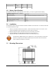

TABLE OF FIGURES
Figure 1: Front View of the GPS-206. Note the SIM Card Access..............................................................8
Figure 2: Back View of the GPS-206..........................................................................................................8
Figure 3: Mounting dimensions of a GPS-206...........................................................................................10
Figure 4: 8-Pin Connections......................................................................................................................12
Figure 5: Garmin FMI section in the DP-1000S........................................................................................15
Figure 6: Auxiliary Expansion Cable Schematic.......................................................................................15
Figure 7: Wiring for Power Only (HRNSxx).............................................................................................18
Figure 8: Wiring for Power and Serial Interface (PRG-xx).......................................................................18
Figure 9: Wiring for Power and I/O...........................................................................................................19
TABLES
Table 1: 8-pin I/O Connector Functionality...............................................................................................11
Table 2: Manufacturer Part Numbers to Build Cables...............................................................................12
Table 3: Auxiliary Expansion Cable Specifications...................................................................................16
© CES Wireless Technologies Corp – 2011 Page 5 of 23