
User manual

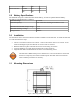

USR1 (Green) – This LED indicates the state of the GSM connection. If blinking the GPS206 is
attempting to establish the connection. If solid the GSM connection has been established.
PWR GPS (Red) – When this LED is illuminated it indicates that the GPS206 has power.
USR2 (Red) – This LED indicates the state of the GPS fix. If illuminated the GPS206 has
established a position fix from satellites in the GPS satellite constellation that are viewable from
its current location.
Figure 1: Front View of the GPS-206. Note the SIM Card Access.
Back View: On the back of the GPS-206 are 3 connectors. On the left is the GPS Antenna connector
(FAKRA Blue Coding C Antenna Connector for 3.3 Vdc GPS). In the middle is the 8-pin I/O
connector (described in detail later in this manual). On the right is the Cellular Antenna (FAKRA
Bordeaux Violet Coding D Antenna Connector for GSM).
Figure 2: Back View of the GPS-206.
© CES Wireless Technologies Corp – 2011 Page 8 of 23