GPS-201 and GPS-202 USER MANUAL CES WIRELESS TECHNOLOGIES, CORP. 925-122 South Semoran Boulevard Winter Park, Florida 32792 October 1, 2010 GPS201-202 Manual v1p1.doc Revision 1.1 © Copyright CES WIRELESS TECHNOLOGIES CORP. (2010) The information contained in this document is subject to change without notice and should not be construed as a commitment by CES WIRELESS TECHNOLOGIES CORP. unless such commitment is expressly given in a covering document.
REGULATORY COMPLIANCE FCC The GPRS modem was tested and certified to meet FCC Parts 15 in a stand-alone configuration, which demonstrated that it complies with Part 15 emission limits. The GPS-201/202 uses an Enfora manufactured GPRS modem. FCC Part 22 & Part 24 is covered by the "modular approval" process for a transmitter.
CHANGE LOG Date 2010-08-05 2010-10-01 Author Doug Hamilton Doug Hamilton Description Initial Release (1.0) Added description of the LEDs in Section 1.
TABLE OF CONTENTS REGULATORY COMPLIANCE.................................................................................................................2 CHANGE LOG .............................................................................................................................................3 TABLE OF CONTENTS ..............................................................................................................................4 1.0 Introduction..........................................
1.0 Introduction The GPS-201 and GPS202 are some of the smallest and most economical GPS asset tracking devices available today. GPS and event data is made available on-board the GPS-201/202 for transmission to FleetLinc (CES web based subscriber fleet management service). Models are market specific and may not operate in certain countries. Consult CES for specific country by country information. 1.
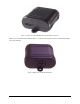
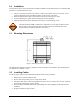
Figure 1: Front View of the GPS-201/202. Note the SIM Card Access. Back View: On the back of the GPS-201/202 is 1 connector. The 8-pin I/O connector (described in detail later in this manual). Figure 2: Back View of the GPS-201/202.
2.0 Specifications Note: Specifications subject to change without notice. 2.1 System Information Dimensions Weight Housing: TX Power: 64.8 x 61 x 25.6mm L x W x H: Rugged plastic enclosure Class 4 (2W @850/900 MHz) Class 1 (1W @1800/1900 MHz) 850/900/1800/1900 Frequency: 2.2 GPRS Packet Data Mode: Protocol: Coding Schemes: Packet Channel: 2.3 Class B, Multislot 10 GSM/GPRS Rel 97 AMR Rel 99 CS1-CS4 PBCCH/PCCCH GPS Functionality Connector: Antenna: 2.
3.0 Installation The instructions in this section describe the hardware installation of the GPS-201/202. To install the GPS201/202 in a vehicle follow these steps: • • • • Choose a convenient location in the vehicle – either in the trunk or interior of a vehicle. Avoid locations that might expose the GPS-201/202 to excessive heat or moisture.
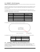
3.2.1 HRNS057 - 8-Pin I/O Connector HRNS057 is an 8-pin external I/O connector and cable. This connector provides power and can be used to interface the GPS-201/202 with other devices. CES Wireless Technologies can also provide optional cables with connectors. The part numbers vary with the cable’s intended use. Please contact your CES Wireless Technologies sales or support executive for more information. You may also build your own cable. Table 1 describes the functionality of this 8-pin connector.
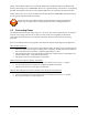
NOTE: Not all GPS-201/202’s are provided with SIM cards. The SIM card will be provided by CES Wireless Technologies only if GSM/GPRS data service is purchased along with the device. If purchasing the SIM card separately take steps to ensure that the SIM card is provisioned by the operator for data. NOTE: Always take care to protect the SIM card. The GPS-201/202’s GSM/GPRS related functionality will not operate without the SIM card installed.
4.0 Support If you need help, we are easily accessible …. Telephone: Call 407-679-9440, and ask for product support. Fax: 407-679-8110 Email: support@ceswireless.com Skype: Please email support@ceswireless.com to obtain your currently assigned support engineer’s Skype address. Product support may ask you to E-MAIL a copy of the programmed parameters to us for analysis. To do this, go to FILE on the DP-1000S main menu, and click on SAVE AS. Note the path to the saved file in the save file dialog.
Appendix 1 – Cable Wiring Diagrams Figure 5: Wiring for Power Only (HRNSxx) Figure 7: Wiring for Power and I/O © CES Wireless Technologies Corp – 2010 Page 12 of 12