
User manual

© CES Wireless Technologies Corp – 2010 Page 5 of 12
1.0 Introduction
The GPS-201 and GPS202 are some of the smallest and most economical GPS asset tracking devices
available today.
GPS and event data is made available on-board the GPS-201/202 for transmission to FleetLinc (CES
web based subscriber fleet management service). Models are market specific and may not operate in
certain countries. Consult CES for specific country by country information.
1.1 About the GPS-201/202
The GPS-201/202 is an Automated Vehicle Locating (AVL) device that utilizes a GSM/GPRS cellular
modem and a Global Positioning Satellite (GPS) module. Working together, these technologies allow the
GPS-201/202 to simultaneously act as a stand alone GPS reporting device and wireless data retrieval unit.
The GPS-201/202 provides a flexible AVL solution one Input and an Ignition Input. The GPS-201/202 is
designed to work as a stand-alone device in a vehicle. It requires DC power. No antennas are required –
they are built in to the GPS-201/202. Please note that the device is not weather, dust or splash proof.
1.2 About This Manual
This manual contains instructions on how to install and configure the GPS-201/202. Please follow the
instructions closely to avoid damaging the GPS-201/202.
1.3 Basic Package Contents
The basic package will contain the following:
• GPS-201/202 - GPS/GSM/GPRS Tracking and Fleet Management Device
• 8-pin interface connector with DC cable (HRNS-057)
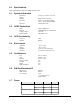
1.4 Accessories
The following accessories are available from CES Wireless Technologies:
• PRG-03 Programming Cable - 8-pin Serial I/O cable with DB-9 Connector
• DP-1000S Programming Software (can be downloaded from the CES FTP site, and is also
available on CD-SOFT1 CD).
1.5 System Requirements
It is necessary to have a computer running Windows 2000, Windows XP or Windows Server 2003 to
program the device. The system must include a serial port in order to configure the GPS-201/202.
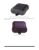
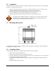
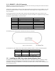
1.6 GPS-201/202 Front and Back View
Front View: On the front of the GPS-201/202 is the GSM SIM Card Access. Note: the SIM Card Lock on
the right side of the access window. To the right of the SIM Card Access are three LEDs. The
functionality of these LEDs is (left to right):
USR1 (Green) – This LED indicates the state of the GSM connection. If blinking the GPS206 is
attempting to establish the connection. If solid the GSM connection has been established.
PWR GPS (Red) – When this LED is illuminated it indicates that the GPS206 has power.
USR2 (Blue) – This LED indicates the state of the GPS fix. If illuminated the GPS206 has
established a position fix from satellites in the GPS satellite constellation that are viewable from
its current location.