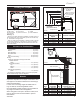
INSTALLER/CONSUMER SAFETY INFORMATION PLEASE READ THIS MANUAL BEFORE INSTALLING AND USING APPLIANCE WARNING! IF THE INFORMATION IN THIS MANUAL IS NOT FOLLOWED EXACTLY, A FIRE OR EXPLOSION MAY RESULT CAUSING PROPERTY DAMAGE, PERSONAL INJURY OR LOSS OF LIFE. Chateau™ Direct Vent Gas Fireplace Model: DVT38IN, DVT44IN FOR YOUR SAFETY Installation and service must be performed by a qualified installer, service agency or the gas supplier. WHAT TO DO IF YOU SMELL GAS: • Do not try to light any appliance.
Chateau™ Table of Contents Please read the installation & operating instructions before using this appliance. Thank you and congratulations on your purchase of a CFM Corporation fireplace. IMPORTANT: Read all instructions and warnings carefully before starting installation. Failure to follow these instructions may result in a possible fire hazard and will void the warranty. Installation & Important Curing/Burning Instructions .........................................................
Chateau™ Installation & Operating Instructions This gas fireplace must be installed by a qualified installer, preferably NFI or WETT (Canada) certified, in accordance with local building codes and with current CSA-B149.1 Installation codes for Gas Burning Appliances and Equipment. For USA Installations follow local codes and/or the current National Fuel Gas Code. ANSI Z223.1/NFPA 54.
Chateau™ Fireplace Dimensions - DVT38IN Rough Opening Depth 54" (1372 mm) 3" (76 mm) 11���" (298mm) 17" (432mm) 8���" Dia. (213 mm) 11" Dia.
Chateau™ Locating Your Fireplace Combustible Framing and Finish Wall Above Standoffs May use combustible facing material in this area V Y E W A B C X Standoff Y X Z Y D A B F LU584-1 Locating unit A) Flat on wall B) Cross corner C) **Island 2/4/99 djt D) *Room divider E) *Flat on wall corner F) Chase installation Y) 6” minimum NOTE (Fig. 3): ** Island (C) and Room Divider (D) installation is possible as long as the horizontal portion of the vent system (X) does not exceed 20’ (6 m).
Chateau™ Hearth A hearth is not mandatory but is recommended for aesthetic purposes. We recommend a noncombustible hearth which projects out 12” (305 mm) or more from the front of the fireplace. The hearth cannot exceed 1¹⁄₂” (38mm) in height from bottom of fireplace for ease of door accessibility. (Fig. 5) Cold climate installation recommendation: When installing this unit against a noninsulated exterior wall or chase, it is mandatory the outer walls be insulated to conform to applicable insulation codes.
Chateau™ Gas Line Installation Gas Specifications Gas Model Fuel Control DVT38IN Natural Gas American Flame DVT38IP Propane AF-4034 DVT44IN Natural Gas with DVT44IP Propane 7.5V DC Hi/Lo Max. Input BTU/hr 46,000 46,000 60,000 60,000 Min. Input BTU/hr 32,000 36,000 37,000 45,000 Gas Inlet and Manifold Pressures Minimum Inlet Pressure Maximum Inlet Pressure Manifold Pressure Natural LP (Propane) 5.5” w.c. 11.0” w.c. 14.0” w.c. 14.0” w.c. 3.5” w.c. 10.0” w.c.
Chateau™ Electrical Junction Box The fireplace, when installed, must be electrically connected and grounded in accordance with local codes or, in the absence of local codes, with the current CSA C22.1 Canadian Electrical Code or the national electrical code ANSI/NFPA No. 70 in the USA. It is strongly suggested that the wiring of the Electrical Junction Box be carried out by a licensed electrician. Ensure the power to the supply line has been disconnected before commencing this procedure. 6.
Chateau™ NOTE: If you need to test the inlet pressure and/or manifold pressure, there are two (2) test ports available along the right side front edge between the firebox side and outer casing. The upper test port is inlet pressure. The lower test port is manifold pressure. (Refer to Figure 8) Learn Button Learn AUX POWER Junction Box IPI Continous Pilot Off/On S Remote/Off I ADJ. Main Module Power Module Main Module FP1792 Fig. 10 Connect 120V AC electrical supply. 16.
Chateau™ Remote Control Transmitter Operating Instructions Introduction This transmitter operating range is approximately 20 feet (6 m). The transmitter operates on one of 1,048,576 security codes that are programmed into the transmitter at the factory; this transmitter operates on radio frequencies with nonTransmitter Wall Clip Slot Off Continuous Pilot Button Mode Button The transmitter operates on (2) 1.5V AAA batteries.
Chateau™ Setting ° F / ° C Scale ����� ���� The factory setting for temperature is ° F. To change this setting to ° C; Press the ON H/L key and the OFF CONTINUOUS PILOT key on the transmitter at the same time. This will change from ° F to ° C. Follow this same procedure to change from ° C to ° F. ��� Manual Function To operate the system in the manual “MODE” do the following: ���� Screen while depressing ON key Screen after 3 second default ON - HI Flame Operation Press and release the ON H/L key.
Chateau™ To Change the Set Temperature Press and hold the SET key until the desired set temperature is reached. (By pressing and holding the set key, the LCD screen set numbers will increase from 45° to 99°, then restart at 45°) ��� ��� ���� ���� Release the SET key. The LCD screen will display the set temperature for 3 seconds, then will flash the set temperature for 3 seconds, then the LCD screen will default to display the room temperature.
Chateau™ Operational Notes: The Thermostatic feature on the transmitter operates the appliance whenever the ROOM TEMPERATURE varies a certain number of degrees from the SET TEMPERATURE. This variation is called the “SWING” or TEMPERATURE DIFFERENTIAL. The normal operating cycle of an appliance may be 2-4 times per hour depending on how well the room or home is insulated from the cold or drafts. The factory setting for the “swing number” is 2.
Chateau™ White or Green Green or White White or Orange Orange or White To Pilot Ignitor Pilot Main Main Module AF-4000 Black Red S DC Motor Learn Button Power Module I To Pilot Flame Sensor Orange Red Brown Black Remote Battery Back-Up Pack Remote/Off Switch Continuous Pilot ON/OFF Switch Black Gnd Brown (SWI) (Optional Brown (SWI) ON/OFF Switch) Red Black FP1795 AC Adaptor Red Black Pulse/Continuous Button Extension Harness Fig. 11 DVT38/44 wiring diagram.
Chateau™ General Venting Information - Termination Location INSIDE CORNER DETAIL V D H A V N N E L V B V F C B ����� ������ ��� ��� V V VENT TERMINATION B V �������� �� B CFM145a G B V ����� ������ V J G X B I A X AIR SUPPLY INLET M V K X G A V V AREA WHERE TERMINAL IS NOT PERMITTED Canadian Installations1 US Installations2 A = Clearance above grade, veranda, porch, deck, or balcony B = Clearance to window or door that may be opened 12” (30 CFM145a cm) 12” (30
Chateau™ Termination Clearances Termination clearances for buildings with combustible and noncombustible exteriors. Inside Corner Alcove Applications* Outside Corner G= Combustible 6" (152 mm) G F= Combustible 6" (152 mm) Noncombustible 2" (51 mm) V Noncombustible 2" (51 mm) V C V E O F Balcony with perpendicular side wall Balcony with no side wall D C E = Min. 6” (152 mm) for non-vinyl sidewalls Min. 12” (305 mm) for vinyl sidewalls O = 8’ (2.4 m) Min.
Chateau™ General Information Assembling Vent Pipes SK8 Venting Pipes Canadian Installations: The venting system must be installed in accordance with the current CSA-B149 .1 installation code. USA Installations: The venting system must conform with local codes and/ or the current National Fuel Gas code ANSI Z223.1/ NFPA 54. Only venting components manufactured by CFM Corporation can be used in Direct Vent systems.
Chateau™ Minimum clearance between vent pipes and combustible materials is 3¹⁄₂” (89 mm) on top, 2¹⁄₂” (64 mm) on both sides and 1¹⁄₂” (38 mm) on the bottom. �� �� �� �� �� When the vent termination exits through foundations less than 20” (508 mm) below siding outcrop, the vent pipe must be flush with the siding.
Chateau™ • The maximum number of 45° elbows permitted per • • side wall installation is two (2). These elbows can be installed in either the vertical or horizontal run. (Fig. 18) For each 45° elbow installed in the horizontal run, the length of the horizontal run MUST be reduced by 18” (45 cm). This does not apply if the 45° elbows are installed on the vertical part of the vent system. For each 90° elbow installed in the horizontal run, the length of the horizontal run MUST be reduced by 36” (914 mm).
Chateau™ STEP 3 X Slide the zero clearance sleeve through the wall and install the firestop on the inside surface of the wall. Secure with four (4) #8 sheet metal screws. STEP 4 Place fireplace into position. (Fig. 22) Measure the vertical height (X) required from the base of the flue collars to the center of the wall opening. NOTE: If using the SK8DVSK Kit, the vertical section of pipe is telescopic and could provide adjustment from 24” up to 40” (610 mm to 1016 mm). FP1241a Fig.
Chateau™ 12' DVT44 - Natural or LP (3.7m) Use 6���" or Greater DVT38 - Natural or LP 'X' Use 5���" Fresh Air Restrictor Plate X Setting 30’ to 40’ #1 20’ to 29’ #2 12’ to 19’ #3 FP1409 FP1243a Fig. 25 Secure termination to wall. Vertical Through-the-Roof Applications Use of Restrictor Plate for Vertical Venting Applications The primary purpose for the vent restrictor is to regain flame height under certain venting conditions as outlined below.
Chateau™ Max. 8' (2.4m) Max. Height 40' (12 m) 4 Max. 20' (6 m) Min. Height 20' (6 m) 1 + 2 + 3 + 4 = 270° 3 2 1 Pipe Straps Every 3’ (914mm) Minimum 2’ (610mm) Before Any Elbow FP1244a Fig. 28 Support straps for horizontal runs. • Up to two (2) 30° or 45° elbows may be used within the horizontal run. For each 30° or 45° elbow used on the horizontal levelFP1244a the maximum horizontal through the roof length must be reduced by 18” (457 mm).
Chateau™ Attic Installation Elbow Strap Nails (4) Support Structure Firestop Spacer Elbow Strap (must be tight) Joist Ceiling Hole Framing Angled Strap Ceiling Installation Angled Firestop Chimney Support Strap (must be tight) Joist FP270/271 FP270/271 Series Fig. 32 Attach straps to a structural CR framing member. 2/19/99 djt Firestop Spacer Nails (4) FP593 Fig. 30 Installing firestop spacer. Attic Insulation Shield Min.
Chateau™ Chimney Components Component Horizontal Starter Kit SK8 Chimney Sections SK8 Chimney Elbows Firestop Zero Clearance Sleeve Attic Insulation Shield Chimney Support Round Top Termination Round Top Termination Extended Flashing Housing Extensions Chase Top Housing Chase Top Housing Horizontal Termination Description Model Number Contains 24”-40” telescopic pipe* for minimum vertical SK8DVSK rise from collar pipe, 90° elbow, horizontal through-wall starter pipe, zero clearance sleeve, metal
Chateau™ Operating Instructions Clean the glass after the first two weeks of operation. Glass Information Only glass approved by CFM Corporation should be used on this fireplace. • The use of any non-approved replacement glass will void all product warranties. • Care must be taken to avoid breakage of the glass. • Do not operate appliance with glass front • Phillips Screws removed, cracked or broken.
Chateau™ Ceramic Refractory Installation Flue Opening The ceramic refractories are fragile and should be handled with care. Due to the size of the refractories, an assistant may be helpful. Restrictor Plate NOTE: The ceramic refractories are shipped separate from the unit but MUST BE installed. Sheet Metal Screws To Remove Outer Ring, Cut Here (6 Places) Refer to Ceramic Refractory Kit listed below. DVT44IN (6³⁄₄” as Shown) Use tin snips to cut along slots to make 4¹⁄₂” (114mm) restrictor plate.
Chateau™ 3. Start with either the right side refractory or left side refractory. Hold the refractory at an angle. Slide and seat the bottom edge toward the bottom of the firebox. Tilt it carefully toward the side until the piece is in place. Slide the refractory forward until it comes in contact with the front flange on the firebox. 4.
Chateau™ DVT44IN Logs Log Rear Right Log Grate Burner Log Front Middle Right Log Burner Overlay Log Rear Left Log Front Right Log Front Upper Right Log Front Left Log Grate Right Log Front Middle Left Log Grate Left Log Rear Upper Middle LG413 Fig. 41 DVT44IN log identification. 1. Position the Log Grate Burner. Remove the two LG413 (2) screws that attach the fettle to the burner. Place DVT44 the log grate burner between the notch on the front Log ID of the burner housing behind the burner tube.
Chateau™ 7. Position the Log Grate Right and Left. Position the right and left grate logs simultaneously on the grate in front of the burner housing by holding the two logs with the narrower end toward the middle and the bark details toward the front. Set the logs and lean forward toward the grate. The outer end of the logs should line up with the grate on the outside. (Fig. 43) 8. Position the Log Rear Right .
Chateau™ Figure 46 Log Front Middle (DVT38) LG407 Figure 47 Log Rear Upper Middle (DVT44IN Log Front Upper Right LG407 DVT38 front middle log 3/05 LG406 12. Position the Log Front Middle Right. DVT38IN only. Hold the log with the pointed end toward the back and the wide end toward the front. Set the rectangular indentation located on the bottom of this log over the third right tine on the grate. Lay the pointed end of the log over the flat area located on the pointed end of the front middle log. (Fig.
Chateau™ Volcanic Rock Small Lava Rock Ember Material LG484 Fig. 48 DVT38IN logset complete. ����� ���������� ���� Small Lava Rock Volcanic Rock Ember Material LG482 Fig. 49 DVT44IN logset complete.
Chateau™ Flame Characteristics SIT Top Convertible It is important to periodically perform a visual check of the pilot and burner flames. Compare them to the illustrations below. (Figs. 50 & 51) If the flame patterns appear abnormal contact a qualified service provider for service and adjustment. FP1777 DVT38 Fig. 50 Correct pilot flame appearance.
Chateau™ Trim Installation CAUTION: Allow fireplace to cool if it has been in operation. Trim components: Top frame assembly, bottom trim assembly, right and left trim assemblies. NOTE: Place trim pieces with magnets facing window frame. Nailing Flange 1. Place bottom trim on the bottom of the window frame. NOTE: Final adjustments will be made once all trim pieces are in place. 2. The right and left trim piece have a 45° notch on the back corner of the top end. (Fig.
Chateau™ Lighting & Operating Instructions For Fireplaces equipped with American Flame Automatic Control System (IN or IP) Warning: If you do not follow these instructions exactly, a fire or explosion may result, causing property damage, personal injury and loss of life. For Your Safety, Read the Following Warnings before Lighting the Appliance A. This fireplace is equipped with an ignition device which automatically lights the pilot and main burner.
Chateau™ Troubleshooting American Flame Gas Control System If erratic system behavior is observed that cannot be resolved by the methods outlined below, ensure that there is not a transmitter with batteries installed that may be interfering. If a transmitter is packed with batteries installed, its buttons may be depressed sending a constant signal which can interfere with the transmission of desired signals. A transmitter with new batteries can have a range of over 100’ (30.4 m).
Chateau™ Troubleshooting American Flame Gas Control System (continued) Main flame will not light • Verify the gas supply is turned on. • Ensure the pilot flame will ignite. If not, see pilot flame troubleshooting above. • Make sure the green and white leads from the module are securely connected to the terminals labeled “MAIN: on the valve body. • Make certain the pilot flame is in contact with the flame rectification sensor on the pilot assembly. This valve is equipped with a pilot flame adjustment screw.
Chateau™ American Flame Gas Control System Error Codes Ignition Safety: Protection for Ignition System Error Code: One beep every one second Description of Fault: Warn users if the pilot is not successfully ignited in 60 seconds. How to Clear: Press OFF then ON buttons to re-attempt ignition. What to Check: • Ensure gas supply is turned on. • Ensure orange/white leads from module are plugged into the “PILOT” connection on the valve body.
Chateau™ Fuel Conversion Instructions WARNING! This conversion kit shall be installed by a qualified service agency in accordance with the manufacturer’s instructions and all applicable codes and requirements of the authority having jurisdiction. If the information in these instructions is not followed exactly, a fire, explosion or production of carbon monoxide may result causing property damage, personal injury or loss of life.
Chateau™ Allen Wrench Index Tab Snap Ring CO134 Fig. 56 Remove pilot orifice. 10. Install the conversion orifice. 11. Reinstall pilot hood. Be sure to align hood with CO134 index tab. AF pilot orifice Converting the Gas3/07 Control Valve The AF4000 electronic control valve is convertible from natural gas to propane gas by changing the minimum rate screw in the valve and by rotating a plastic knob located under a black cap on the top face of the valve. 1.
Chateau™ Table 1 Injector Orifice Size Matrix Kit # 20011992 Model DVT38IP 20012367 DVT44IP Front Part # #66 20009182 (.033”) #63 20006251 (.037”) Conversion to LP Burner Orifice Middle Part # #59 20000664 (.041”) #57 20004587 (.043”) Input (BTU/hr) Rear Part # Minimum Maximum #50 30000337 34,000 46,000 (.070”) #49 20006252 45,000 60,000 (.
Chateau™ Maintenance Burner and Burner Compartment It is important to keep the burner and the burner compartment clean. At least once per year the logs and lava rock/ember material should be removed and the burner compartment vacuumed and wiped out. Remove and refit the logs as per the instructions in this manual. Always handle the logs with care as they are fragile and may also be hot if the fireplace has been in use.
Chateau™ 1 DVT38 1 DVT44 1i 1e 1c 1d 1d 1a 1g 1c 1b 1j 1b 1j 1g 1n 1e 1d 1f 1h 1k 1o 1a 1n 1h 1k 1o 1i 1l 1l 1p 1p 1m 1m 2 6 3 7 5 15 18 13 12 11a,b 16 10a,b 8 9a,b 19 20 14 21 9a,b 10a,b 22 11a,b ON H/L OFF/CONTINUOUS PILOT BUTTON 23 4a 4b 24 4c 4d 4e 25 28 30d 30b 26 30c 30a 17 30 11956 CFM Corporation reserves the right to make changes in design, materials, specifications, prices and discontinue colors and products at any time, DVT38/44 parts wi
Chateau™ DVT38IN, DVT44IN Ref. 1. 1a. 1b. 1c. 1d. 1e. 1f. 1g. 1h. 1i. 1j. 1k. 1l. 1m. 1n. 1o. 1p. 2. 3. 4. 4a. 4b. 4c. 4d. 4e. 5. 6. 7. 8. 9a. 9a. 9b. 9b. 10a. 10a. 10b. 10b. 11a. 11a. 11b. 11b. 12. 13. 14. 15. 16.
Chateau™ DVT38IN, DVT44IN Ref. 17. 18. 19. 20. 21. 22. 23. 24. 25. 26. 27. 28. 29. 30. 30a. 30b. 30c. 30d. 31.
Chateau™ Accessories Back-up Battery Kit All Models: DVTBBK Follow instructions provided with the kit or on Page 9 for installation. 20011956 Ceramic Refractory Kits Ceramic refractory panels are available in kit form for the DVT38IN and DVT44. Fireplace Kit Model Description DVT38IN DVT38CRR Colonial Red DVT38IN DVT38CRL Limestone DVT38IN DVT38CRH Herringbone DVT44IN DVT44CRR Colonial Red DVT44IN DVT44CRL Limestone DVT44IN DVT44CRH Herringbone Follow instructions on Page 21 for installation.
Chateau™ 46 20011956
LIMITED LIFETIME WARRANTY Chateau™ PRODUCT COVERED BY THIS WARRANTY All Vermont Castings brand gas stoves, gas inserts, and gas fireplaces installed in the United States of America or Canada.
Efficiency Ratings Model DVT38IN DVT38IP DVT44IN DVT44IP EnerGuide Ratings Fireplace Efficiency (%) 48.2 48.2 51 51 CFM Corporation 410 Admiral Blvd. • Mississauga, Ontario, Canada L5T 2N6 800-668-5323 • www.cfmcorp.