MS/TP Communications Bus Technical Bulletin Code No. LIT-12011034 Software Release 7.0 Issued March 13, 2015 Refer to the QuickLIT website for the most up-to-date version of this document. Document Introduction.............................................................................................................3 Related Documentation.............................................................................................................3 MS/TP Bus Overview........................................
Surge Protectors......................................................................................................................44 Appendix: Maximizing and Troubleshooting the MS/TP Bus..............................................47 Maximizing Tips.......................................................................................................................47 MS/TP Bus Health Factors of the Diagnostics Tab...............................................................47 Bus Health Index......
Document Introduction The BACnet® protocol Master-Slave/Token-Passing (MS/TP) communications bus is a local network that connects supervisory controllers and field controllers to field point interfaces. This document describes the specifications, device limits, and rules of the MS/TP communications bus, as well as how to wire and terminate devices, and troubleshoot device communication on the MS/TP bus. The remote MS/TP field bus is also described.
Table 1: Related Documentation For Information On See Document Installation and Specifications of the VMA1610, VMA1620, VMA1610 and VMA1620 Variable Air Volume Controllers VMA1615, VMA1630, VMA1617, and VMA1632 Installation Instructions (Part No. 24-10143-20) VMA1615 and VMA1630 VAV Controllers Installation Instructions (Part No. 24-10143-217) VMA1832 VAV Controller Installation Instructions (Part No.
MS/TP Bus Overview The MS/TP bus is based on BACnet® standard protocol SSPC-135, Clause 9. The BACnet MS/TP protocol is a peer-to-peer, multiple master protocol based on token passing. Only master devices can receive the token, and only the device holding the token is allowed to originate a message on the bus. The token is passed from master device to master device using a small message. The token is passed in consecutive order starting with the lowest address.
FC Bus An FC bus connects a Metasys® system NAE or NCE to FACs, FECs, VMA16s, IOMs, and TEC26xx Series thermostats. Third-party BACnet MS/TP devices can also be connected to the FC bus. Figure 1: Example of an MS/TP Communications Bus On an FC bus, the NAE or NCE is the bus supervisor. An FC bus supports up to three bus segments that are connected with network repeaters (Figure 9). See Local FC Bus Rules and Specifications for more information.
Remote Field Bus The Remote Field Bus uses a BACnet Router to connect remote BACnet MS/TP devices such as FECs and VMA16s to the Metasys network. These devices include FACs, FECs, VMA16s, IOMs, TEC26xx Series thermostats, and other BACnet MS/TP field devices. Although several routers from different manufacturers are available, the recommended device is the LIP-ME201™ BACnet Router from Loytec Electronics GmbH.
The Remote Field Bus is defined at a Metasys NxE supervisory engine or Open Data Server (ODS) Workstation (Figure 3) through field bus integration, similar to how a local MS/TP field bus is added. The Remote Field Bus appears on the All Items Navigation tree in the Site Management Portal UI. You can also provide a custom name to clearly identify the type of integration.
• • Remote buildings where an MS/TP bus is not already available, but an Ethernet BACnet/IP network is (for example, university or hospital campuses) Sites with a reliable network between buildings that do not need to have a separate NAE for the building (for example, school districts) Note: The ZFR1800 Series Wireless Field Bus System is not supported on the Remote Field Bus.
Table 2: BACnet Router Attributes BACnet Router Attribute Name Description Network Number (for Ethernet BACnet/IP) A unique identifier defined for the BACnet IP network connection on the BACnet Router. The supervisory engine uses this number to locate the device. User Action or Recommended Setting Specify the network number assigned for BACnet/IP connections to the BACnet network. Do not use 2000 or 65000 as the network number; these numbers are used for existing embedded networks.
Table 2: BACnet Router Attributes BACnet Router Attribute Name Description User Action or Recommended Setting MS/TP MAC Address The MS/TP MAC address of the BACnet default=0 Router you select must not conflict with any other MS/TP device on the same wire. Address zero (0) is generally recommended. For other field devices connected to the same RS-485 MS/TP bus, use sequential addressing following the Metasys MS/TP bus addressing recommendations and reserved addresses.
Figure 4: Setting Network Address or Network Number Supervisory Engine Configuration for Adding Remote Field Bus You define the Remote Field Bus at a Metasys supervisory engine much like you define a local field bus. Important settings include Trunk Number and Network Address.
Trunk Number On a supervisory engine, trunk numbers 1 and 2 are reserved for the local field bus integration. Trunk numbers 3 to 20 are reserved for Remote Field Bus integrations. The quantity of field buses supported on any particular device varies according to the specific device in use. Generally, the number of supported trunks is less than the maximum trunk number allowed (Table 3). For example, an ODS supports 16 field buses maximum, not 20 field buses as the trunk number range would suggest.
Figure 5: Wiring BACnet Router Remote Field Bus Restrictions Compared to the local MS/TP field bus, the Remote Field Bus has several operational restrictions. Number of Field Controllers on a Remote Field Bus The number of controllers that can successfully operate on a Remote Field Bus is generally less than that of a local field bus, and is heavily dependent on the capabilities of the router used. Generally, a good quality router can support at least 10 BACnet MS/TP devices, and some can support more.
Field Controller Main Code Release For Remote Field Bus compatibility, the Main Code for the field controllers you connect to remotely must be at Metasys system Release 5.3 or later. Remote field bus communication is not as robust with controllers that are running older releases of the Metasys system. CCT Pass Through Loading Generally, you can upload and download code and applications with CCT Pass Through for devices directly connected to a Remote Field Bus (subject to router message load levels).
The Clear Statistics command is redirected to the FEC Family BACnet Device used for collecting MS/TP trunk statistics. If the device used for collecting statistics changes after this command is issued, the new device is not cleared unless the command is issued again. Sync Field Device Time(s) The Sync Field Device Time(s) command sends a high-priority time synchronization command to all child BACnet Integration devices, based on each device mapper object's Manual Time Sync Type attribute.
Figure 6: EOL Terminations on an MS/TP Bus Baud Rates on the MS/TP Bus An MS/TP bus can be configured to communicate at one of four different baud rates. All of the devices on an MS/TP bus must communicate at the same baud rate. The baud rate setting determines the rate at which devices communicate data over the bus. The baud rate settings available on Metasys MS/TP devices are 9600 bps, 19.2 kbps, 38.4 kbps, 76.8 kbps, and Auto. The baud rate setting for Metasys devices is set in the Metasys software.
If you anticipate critical peer-to-peer communication and therefore do not want field controllers to wait for the bus supervisor to establish the baud rate, you can specify the baud rate for each device immediately at startup. Choose the baud rate carefully if you use this method, since changing it requires changing each device separately. TEC26xx Series thermostats automatically set their baud rate to the bus supervisor’s baud rate.
The device address set on the ADDRESS DIP switch block applies to the device connection on the bus where the device is not the bus supervisor. For example, the DIP switches on FACs, FECs, or VMA16s (master devices) set the device address for the device connection to the FC bus (or Remote Field Bus). If the FAC, FEC, or VMA16 also supervise an SA bus, the FAC's, FEC's, or VMA16's address on an SA bus is 0 by default (Figure 7).
Table 4: Valid MS/TP Bus Address Values and Address Ranges for MS/TP Bus Devices Address Value/ Address Class Devices Range 0 Bus Supervisor FC Bus: NAE or NCE SA Bus: FAC, FEC, VMA16, or NCE Remote Field Bus: BACnet Router 1 Reserved Wireless Commissioning Converter (MS-BTCVT-1) 3 Reserved for future use ZFR1810 Wireless Field Bus Coordinator 120-127 Reserved for future use 4–127 Master Range FC Bus: FACs, FECs, VMA16s, IOMs, TECs, and non-FX family devices Remote Field Bus: FACs, FECs, VMA16s
Important: On FAC, FEC, VMA16, and IOM Series controllers only, the 128 DIP switch on the controller’s device address DIP switch block is a mode switch used to enable the controller to operate in a wireless mode using the ZFR1800 Series Wireless Field Bus System. On any FAC, FEC, VMA16, or IOM Series controller that is hardwired to an MS/TP Bus, set the 128 DIP switch to the OFF position.
Table 5: Local FC Bus Rules Category Rules/Limits General NAE55 Series models can support up to two local FC buses. Note: When a second FC bus is added to the NAE, be sure the trunk number has not been used on the NAE and enter a Network Address that is unique for the entire site. This applies for any model of NAE. NAE45 Series models can support one local FC bus.
Table 5: Local FC Bus Rules Category Rules/Limits Recommended Cable 22 AWG Stranded, 3-Wire Twisted, Shielded Cable EOL Termination The EOL switch must be set to On (or an EOL terminator installed) on the two devices located at either end of each bus segment on an FC bus. The EOL switches must be set to Off (or EOL termination disabled) for all other devices on the bus segment on an FC bus. See EOL Termination on the Local FC Bus for more information.
Table 6: FC Bus Specifications Category Transient Immunity Specification Meets EN61000-4-4 and EN6100-4-5 requirements for heavy industrial applications. Protected against misapplication of 24 VAC. EOL Termination Method Integral EOL Termination switch or add-on EOL Terminator module (See EOL Termination on the Local FC Bus.) Do not use third-party EOL termination. Shield Grounding Only one hard ground connection per bus segment when using shielded cable. (See Grounding the Bus Cable Shield.
EOL Termination on the Local FC Bus The FC bus requires EOL termination at the end of each bus segment. Figure 10 shows four examples of EOL termination on the FC bus. Figure 10: FC Bus Segment EOL Termination Scenarios Note: Set the EOL termination switch on a repeater’s device connection to ON only when the repeater connection terminates a bus segment. See Scenarios 3 and 4 in Figure 10.
EOL Terminator Module The MS-BACEOL-0 RS485 EOL Terminator provides EOL termination on FC bus segments when the device connected at the end of a bus segment does not have integral EOL termination capability. The EOL terminator is a compact, lightweight, module wrapped in a protective cover that can be quickly installed in a variety of ways. The EOL connects directly to the terminating device on a bus segment with the attached wire leads.
SA Bus Rules and Specifications The SA bus connects IOMs, VSDs, and NS-Series network sensors to field controllers. Figure 11 shows three SA bus examples. Table 7 and Table 8 provide SA bus rules and specifications. Table 7: SA Bus Rules Category Rules/Limits General Each bus supervisor supports one SA Bus (and each SA Bus is a single segment). Number of Devices Supported on the Bus An SA Bus supports up to 10 devices.
SA Bus Device Limits The SA Bus is limited to 10 devices total to ensure good communication on the bus and is limited to four NS sensors because only four unique addresses can be set on the sensors. Due to change of value (COV) limitations, it is best to limit the number of IOMs on the SA Bus to four. The SA bus is also limited by the total power consumption of the devices connected on the bus. Exceeding the total power consumption limit can cause poor bus communication and cause devices to go offline.
EOL Termination on the SA Bus On an SA bus, the minimum requirement is that EOL termination must be enabled on at least one device. Since an SA bus supervisor always has EOL termination enabled, this requirement is always met; however, for enhanced bus performance, we recommend that you enable EOL termination on the devices at each end of the SA bus. See Figure 11 for SA bus EOL termination scenarios.
SA Buses with Multiple Network Sensors An SA bus supports up to four network sensors. Figure 12 shows an example of two SA buses, each with four network sensors. To place multiple network sensors on the bus, three of the network sensors must be DIP switch addressable. Note: Do not mix RJ-style modular (phone) jack and screw terminal devices on the SA bus.
Remote Field Bus Rules and Specifications Table 10 provides rules for the Remote Field Bus (RFB). In addition to these rules: • • • • • • • Configure the BACnet Router before you connect it to the building network. If the BACnet Router is commissioned using IP, use an Ethernet patch cable. For each Remote Field Bus you add to an NAE, make sure the trunk number has not been used on the NAE. Enter a Network Address between 1 and 65534 that is unique for the site.
Table 10: Remote Field Bus Rules Category Rules/Limits Cable Length for FC Bus and Bus Segments When all of the devices connected on the Remote Field Bus are Metasys FACs, FECs, VMA16s, or IOMs, the cable length limits (using 22 AWG 3-wire twisted, shielded cable) are as follows: • Each bus segment can be up to 1,520 m (5,000 ft) in length. • Each RFB can be up to 4,750 m (15,000 ft) in length.
EOL Termination on the Remote Field Bus The Remote Field Bus requires EOL termination at the end of each bus segment. Figure 13 shows four examples of EOL termination on the remote FC bus. Figure 13: Remote Field Bus Segment EOL Termination Scenarios Note: Set the EOL termination switch on a repeater’s device connection to ON only when the repeater connection terminates a bus segment. See Scenarios 3 and 4 in Figure 13.
EOL Terminator Module for Remote Field Bus An EOL terminator is required in all Metasys MS/TP applications wherever a terminating device on a Remote Field Bus segment does not have integral EOL termination (for example, TEC26xx Series thermostats and some BACnet IP Routers). For Metasys devices without a built-in EOL switch, use the MS-BACEOL-0 RS485 EOL Terminator. The EOL terminator is a compact, lightweight module wrapped in a protective cover that can be quickly installed in a variety of ways.
Table 11: Cable for FC Buses and SA Buses in Order of Preference Bus and Cable Type Non-Plenum Applications Plenum Applications Part Number O.D. Part Number O.D. FC Bus: 22 AWG Stranded, Anixter: 3-Wire Twisted Shielded CBL-22/3-FC-PVC 1 Cable Belden®: B5501FE 0.138 in. Anixter: CBL-22/3-FC-PLN 0.140 in. SA Bus (Terminal Block): 22 AWG Stranded, 4-Wire, 2 Twisted-Pair Shielded 1 Cable Anixter: CBL-22/2P-SA-PVC 0.209 in.
Table 12: FC Bus Wire Gauge and FC Bus Baud Rate 22 24 26 Maximum Cable Length per Bus Segment (m [ft]) 1,524 (5,000) 1,524 (5,000) 1,524 (5,000) 1,524 (5,000) (A) (A) (Best) (A) Maximum Number of Nodes (per Segment / per FC Bus) 25/25 50/50 50/100 50/100 (A) (A) (Best) (A) Maximum Cable Length per Bus Segment (m [ft]) 1,524 (5,000) 1,524 (5,000) 1,524 (5,000) 1,524 (5,000) (APR) (APR) (APR) (APR) Maximum Number of Nodes (per Segment / per FC Bus) 25/25 50/50 50/100 50/100
Figure 14: FC Bus and SA Bus Terminal Block Wiring Details Grounding the Bus Cable Shield Inductive interference and Radio Frequency (RF) interference can adversely affect MS/TP applications, causing poor bus performance and frequent device offline occurrences. Experience has shown that installing a properly grounded shielded bus cable in MS/TP applications greatly reduces the impact of ambient inductive noise and RF interference.
Note: The majority of properly grounded MS/TP applications do not require soft ground connections, but you should assess the potential interference that your application may encounter (before you install the bus). It is more efficient to prepare for soft ground connections when making the bus terminations at the initial installation than to return and do it later.
Figure 16: 6-Pin Modular Jack Pinout Details Commissioning Devices on the MS/TP Bus Commission the devices on the local and remote MS/TP buses using the CCT software. Refer to CCT Help (LIT-12011147) for information on commissioning an MS/TP bus application. Applications and device configurations are downloaded to the hardware from the CCT computer using the Wireless Commissioning Converter or through the NAE, NCE, or Open Data Server (ODS) from the Metasys UI.
Appendix: FC Bus Auxiliary Devices Repeaters Repeaters are optional components on the FC Bus that increase the maximum allowable length and device counts of the FC Bus. One repeater is counted as one device on the FC Bus. Repeaters are not allowed on the SA Bus. Table 13 describes how the length and device maximums of the bus change when you add repeaters. The repeater is specified in Local FC Bus Rules and Specifications. A maximum of two repeaters can be between any two points on the FC Bus.
Figure 17: Configuring the Repeater Fiber-Optic Modems You can install the 2110 fiber-optic modems in any location on the FC bus. Just as only two repeaters can be cascaded on the FC bus, only two pairs of 2110 modems can be cascaded. The first installation step is to route the optical fiber and connect each modem to the ends of the fiber. The second step is to connect the FC bus on both sides of the modems.
Fiber Modem between Two Segments If you need to place the 2110 modem between two segments of MS/TP bus, wire a stub length of 6 inches or fewer as shown in Figure 19, and terminate the two pairs of MS/TP bus cable at the end of the stub length. If the fiber modem is at the end of a segment, set the EOL to In. Figure 19: Connecting 2110 Modem in between Two MS/TP Bus Segments Setting Termination on Fiber Modems The 2110 modem does not have an EOL jumper.
Figure 20: Female Modem Cable Connector: EOL Set to In Modem Set EOL to Out To set the modem with the end-of-line selection set to Out, wire the 9-pin connector using solder connections as in Figure 21. Note: The following figure shows the 9-pin female connector. The pin numbers on the 9-pin male connector are reversed.
Surge Protectors Surge protection is strongly recommended if the MS/TP bus is wired between buildings. The protection is provided by a voltage surge suppressor, which is installed on the MS/TP bus near the MS/TP device. Example applications are shown in Figure 22. Figure 22: Surge Protector Installation on MS/TP Bus Note: Fiber-optic bus connections between buildings are immune to transient voltage and other problems associated with hard-wire bus connections.
Table 16: Surge Protector Specifications Category Specification Maximum Energy Dissipation 80 Joules per conductor (10/1000 us) Maximum Operating Voltage 12 VDC Protection Common and normal modes Suppression Voltage Levels (Common mode) 100 kHz ringwave at 200 A: 15.8 volts 100 kHz ringwave at 500 A: 16.8 volts 3 kA combination wave: 20.
The surge protector consists of two sections: the terminal block and the main assembly. These sections separate to make the unit easier to install and replace (Figure 24). Figure 24: Sections of Surge Protector The surge protector is wired depending on which device requires protection. Follow these general steps: 1. Mount the Transient Eliminator device per local codes. Install in an enclosure (if required) as close as possible to the first MS/TP device connecting the trunk segment entering the building.
Appendix: Maximizing and Troubleshooting the MS/TP Bus Maximizing Tips Observe the following guidelines to maximize the performance of an MS/TP bus. Guideline Description Limit the Number of Change of Value COV reports account for the highest amount of traffic on the bus. For best (COV) Report Rates over the MS/TP Bus performance, keep the COV rate at 500 COVs per minute or fewer for each network.
Figure 25: MS/TP Object Diagnostic Tab Bus Health Index The Bus Health Index is a snapshot of the immediate number of errors on the bus. This index provides a weighted moving average of four MS/TP bus error counters: Framing Errors, Header CRC Errors, Data CRC Errors, and Lost Tokens. The ideal value for the Bus Health Index is zero. Because the average is reevaluated every 30 seconds, the average gradually returns to zero if no new errors occur.
Bus Performance Index The Bus Performance Index provides a snapshot of the performance of the network by taking the weighted moving average of the ratio of the actual loop time to the predicted loop time. The Weighted Bus Performance Constant attribute is an adjustment factor that determines how quickly the index changes when the actual loop time changes. Because a master device is allowed to originate messages only when it holds the token, the token loop time is closely related to network performance.
Table 18: Statistics Attributes Attribute Error Condition Indicated Buffer Overflows The node is trying to send or receive too much at this time. Lost Token Network disruption (includes initial startup, so 1 is common) Retries Problems passing the token message Analyze Field Bus Command The Analyze Field Bus command provides detailed information about the devices that currently reside on the local or remote MS/TP bus.
Table 19: Bus Device Configuration List Label Description Object Name Possible Values/Exception Values Displays the name of the field device. The name is Any name or number derived from following in this order: 1. If the field device appears in the navigation tree, the name on the tree is used initially. 2. If the device is communicating on the field bus, its name is read directly and overwrites the current name. 3.
Table 19: Bus Device Configuration List Label Description Code State Possible Values/Exception Values Indicates the state of the operating code within Boot indicates that the device is starting and Johnson Controls® field devices. This field is is not completely functional. meaningful only for Johnson Controls field devices. Main indicates that the device is functional and operating. Unknown indicates that the device is not responding or does not support the Code State attribute.
Check for duplicate addresses in the following ways, depending on the severity of the situation: • • If bus performance is degraded, check the address switch settings at the devices with unreliable communications.
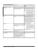
Table 20: Common Problems Symptom Possible Causes Devices Go Offline Device Does Not Come Online • Device is failing to respond to the NAE's request. • Power or other failure occurred at the device. • Communication is disabled at the device. • Multiple integrations (Remote Field Bus integration or BACnet integration) are using the same BACnet Router. • More than one supervisory device is using the same BACnet Router. • The device may be connected to the wrong bus.
• • • • Check for and correct unstable sensors. Reduce the number of devices on the bus, if possible. If running at less than 38.4k baud, increase the baud rate (if possible). Verify repeaters, if applicable. - Verify that repeaters are used where needed. Verify that repeaters are configured and wired correctly. Verify that BACnet Routers are associated with a single integration (Remote Field Bus) at a single supervisory device.
Figure 27: MSTP Master Summary Showing Baud Rates Counting the COVs You can check the COV report rates on the main device object Diagnostics tab of each device that supports this measurement. The two attributes are COV Tx Rate and COV Rcv Rate. The NAE COV Rcv Rate is the total for all connected networks including the Ethernet and should not exceed 500 per minute. The COV Tx Rate counts only the reports originated by this device.
The device remains offline until you repeat this procedure and send the Enable command. Changing the Baud Rate of an Entire Bus The following procedure represents recovery steps to synchronize the baud rate on the MS/TP bus.
In some cases, there are statistical counters that count when recovery actions have been taken. The following sections define four resources monitored by the BACnet software and describe what you may notice if the resource throughput is reduced. The Object Engine Input Queue The Object Engine Input Queue handles all incoming messages intended for object level operations. The Object Engine processes these messages in order by priority, one at a time.
Protocol Engine Output Pending Queue The BACnet® Protocol Engine has an output pending queue used to hold messages when slower communications links, such as MS/TP, are not able to keep up with the rate at which outgoing messages are generated. If this queue becomes too large, the time required to send a message becomes excessive, resulting in slow operation. When this slow operation occurs, applications begin to encounter errors and some devices may drop offline.