AcQuisition Technology bv Headquarters: Raadhuislaan Rijnstraat 20 27a 5341 5347 GL KN Oss Oss Postal address: P.O Box 627 5340 AP Oss The Netherlands Phone: Fax: E-mail: Web: +31-412-651055 +31-412-651050 info@acq.nl http://www.acq.nl i4000 Quad M-module carrier for VMEbus User Manual Version 1.
i4000 - Quad M-module carrier for VMEbus User Manual Version: 1.2 Copyright statement: Copyright ©2005 by AcQuisition Technology bv - OSS, The Netherlands All rights reserved. No part of this publication may be reproduced, transmitted, transcribed, stored in a retrieval system, or translated into any language, in any form or by any means without the written permission of AcQuisition Technology bv.
i4000 - Quad M-module carrier for VMEbus User Manual Version: 1.2 CONTENTS 1. INTRODUCTION . . . . . . . . . . . . . . . . . . . . . . . . . . . . . . . . . . . . . . . . . . . . . . . . . . . . . . . . . . . . . . . . 5 1.1. VALIDITY OF THE MANUAL . . . . . . . . . . . . . . . . . . . . . . . . . . . . . . . . . . . . . . . . . . . . . . . . . . 5 1.2. PURPOSE . . . . . . . . . . . . . . . . . . . . . . . . . . . . . . . . . . . . . . . . . . . . . . . . . . . . . . . . . . . . . . 5 1.3. SCOPE . . . .
i4000 - Quad M-module carrier for VMEbus User Manual Version: 1.2 AcQuisition Technology bv P.O.
i4000 - Quad M-module carrier for VMEbus User Manual 1. INTRODUCTION 1.1. VALIDITY OF THE MANUAL Version: 1.2 This is edition 1.2 of the i4000 user manual and applies to the following boards: • The i4000 VME M-module carrier board without P2 of revision R4 ( i4000 Rev 4 ) • The i4000 VME M-module carrier board with P2 of revision R2 ( i4000/R2 ) The revision can be found on the printed circuit board. 1.2.
i4000 - Quad M-module carrier for VMEbus User Manual Page 6 of 25 Version: 1.2 AcQuisition Technology bv P.O.
i4000 - Quad M-module carrier for VMEbus User Manual 2. PRODUCT OVERVIEW 2.1. INTRODUCTION Version: 1.2 The i4000 provides a compact high-performance VMEbus gateway to the M-module interface. The i4000 has a 6U form factor. Four M-modules can be mounted on the i4000. The M-module interface of the i4000 complies with the M-module Specification. The M-module specification is ANSI approved. The M-module interface features A8, A24, D16 and D32 access types. 2.2.
i4000 - Quad M-module carrier for VMEbus User Manual Page 8 of 25 Version: 1.2 AcQuisition Technology bv P.O.
i4000 - Quad M-module carrier for VMEbus User Manual 3. INSTALLATION AND SETUP 3.1. UNPACKING THE HARDWARE Version: 1.2 The hardware is shipped in an ESD protective container. Before unpacking the hardware, make sure that this takes place in an environment with controlled static electricity.
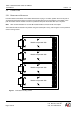
i4000 - Quad M-module carrier for VMEbus User Manual 3.2. Version: 1.2 CONNECTORS 3.2.1. MOUNTING AN M-MODULE Four M-modules can be fitted on the i4000 carrier board. To plug in a module, position the 2-row 40 pole or 3-row 60-pole M-module interface connector of the module above the 2-row header P1 of the i4000. Then push the module until the header connector is positioned and press the module with care in its place.
i4000 - Quad M-module carrier for VMEbus User Manual Version: 1.2 3.2.2. P2 CONNECTOR ASSIGNMENTS (I4000/P2 ONLY) Peripherals can be connected to M-modules in two ways. On the front of the M-module a 25-pole sub-D connector (or mechanically equivalent) can be used to connect cables on the front panel of the VMEbus base board. Alternatively a 24-pole header connector interfaces the I/O signals to the base board where they are connected to the VMEbus P2 connector.
i4000 - Quad M-module carrier for VMEbus User Manual Version: 1.
i4000 - Quad M-module carrier for VMEbus User Manual Version: 1.2 3.2.3. M-MODULE INTERFACE CONNECTOR The following table provides signal names for the M-module male connector that is used by the i4000. The connector consists of two rows of pins labelled rows A and B. The M-module specification also defines a third row (C). This row is rarely used and not available on the i4000. When an M-module with row A, B and C is used, row C is left unoccupied.
i4000 - Quad M-module carrier for VMEbus User Manual Page 14 of 25 Version: 1.2 AcQuisition Technology bv P.O.
i4000 - Quad M-module carrier for VMEbus User Manual 4. VMEBUS INTERFACE 4.1. ADDRESS INTERFACE Version: 1.2 The i4000 can be selected to accept either short addressing, using 16-bit addresses (A16) or standard addressing, using 24-bit addresses (A24). When using short addressing up to 32 i4000 boards can be put in a single VMEbus system since the lower 11 address lines (A0-A10) are used internally on the i4000. If standard addressing is used, a larger address space is available to select the board.
i4000 - Quad M-module carrier for VMEbus User Manual 4.2. Version: 1.2 THE INTERRUPTER The i4000 has a interrupter which is largely compatible with the MC68C153. The interrupter is a so called D08(O) type interrupter which means that the interrupter during an interrupt acknowledge cycle will put a status byte on the data lines D0-D7. The interrupter uses a fixed interrupt level (IRQ1-IRQ7 set by SW1) for all M-modules.
i4000 - Quad M-module carrier for VMEbus User Manual 4.3. Version: 1.2 DIPSWITCH LOCATIONS The location of the dip switches to select the base address (SW2 and SW3) and the dip switch to select the interrupt request level (SW1) can be found at the following locations: i4000/NP2 SW 1 SW 3 SW 2 i4000/P2 SW 1 SW 3 SW 2 Figure 6 AcQuisition Technology bv P.O.
i4000 - Quad M-module carrier for VMEbus User Manual 4.4. Version: 1.2 VMEBUS P1 CONNECTOR ASSIGNMENTS The following table provides signal names for the VMEbus P1 connector as used by the i4000. The connector consists of three rows of pins labelled rows A, B and C.
i4000 - Quad M-module carrier for VMEbus User Manual 5. FUNCTIONAL DESCRIPTION 5.1. BLOCK DIAGRAM Version: 1.2 Figure 7 i4000 block diagram The interrupt controller used on the i4000 is largely compatible with the MC68153 interrupt controller from Motorola. The interrupt controller provides means for the modules to ask for an interrupt of the processor activity and receive service from the processor.
i4000 - Quad M-module carrier for VMEbus User Manual Version: 1.2 5.1.2. ADDRESS MAPPING As mentioned before the address space occupied by the i4000 board is 0x800 bytes (A0-A10). These 0x800 bytes are divided into 4 identical spaces. Every 0x200 bytes block is assigned to a module slot. The first 0x100 bytes address space are assigned to the module itself and the second 0x100 bytes are used for the access part of the interrupt controller.
i4000 - Quad M-module carrier for VMEbus User Manual Version: 1.2 5.1.3. CONTROL REGISTER Control Register 7 6 5 4 3 2 1 0 RES RES X/IN IRE IRAC L2 L1 L0 u u u u u u u Reset: u Write only L2-L0 (Interrupt level) The least significant 3-bit field of the register determines the level at which an interrupt will be generated. These three bits are only used in the i4000/NP2 interrupt controller, if the interrupt level dipswitches are set to software irq level (all “on”).
i4000 - Quad M-module carrier for VMEbus User Manual Page 22 of 25 Version: 1.2 AcQuisition Technology bv P.O.
i4000 - Quad M-module carrier for VMEbus User Manual 6. ANNEX 6.1. COMPONENT IMAGE Version: 1.2 Figure 8 i4000/NP2 component view 6.2. BIBLIOGRAPHY M-Module Standard: ANSI/VITA 12-1996, M-Module Specification; VITA, PO Box 19658, Fountain Hills, AZ 85269, USA Phone (1)(480)8377486 http://www.vita.com APIS Programmer’s Manual AcQuisition Technology P.O. Box 627, 5340 AP Oss, The Netherlands. AcQuisition Technology bv P.O.
i4000 - Quad M-module carrier for VMEbus User Manual 6.3. Version: 1.2 TECHNICAL DATA Slots on the base-board: Up to four modules can be plugged onto the baseboard. A huge number of baseboards in one VME system is supported. Connection: To base-board via VME connector. 4 x M-module interface. M-module I/O-connector accessible through VME bracket. Power supply: +5VDC (+-5%), typical 300mA (without modules). +12VDC, 0mA (without modules) -12VDC, 0mA (without modules) Temperature range: Operating: 0..
i4000 - Quad M-module carrier for VMEbus User Manual AcQuisition Technology bv P.O. Box 627, 5340 AP Oss, The Netherlands Version: 1.